Trunk Options
Three trunk methods and their encapsulation methods were described in the previous sections. Fast Ethernet and Gigabit Ethernet use ISL or 802.1Q encapsulation. FDDI trunks encapsulate with a Cisco proprietary adaptation of 802.10. With ATM, you can use LANE encapsulation. Optionally, you can augment LANE operations with MPOA. Which option should you use?
Criteria you need to consider include the following:
Existing infrastructure
Your technology comfort level
Infrastructure resiliency needs
Bandwidth requirements
Existing Infrastructure
Your trunk choice might be limited to whatever technology you currently deploy in your network. If your Catalyst interfaces are Ethernet and Fast Ethernet, and your cabling is oriented around that, you probably elect to use some form of Ethernet for your trunk lines. The question becomes one, then, of how much bandwidth do you need to support your users.
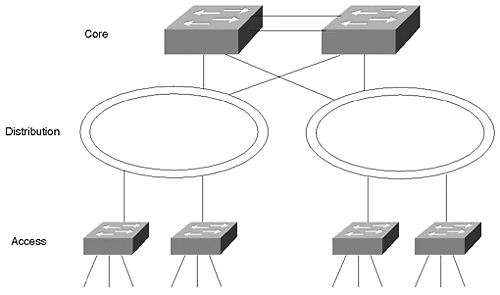
If your backbone infrastructure currently runs FDDI, you might not be able to do much with other trunk technologies without deploying some additional cabling. You might need to shift the FDDI network as a distribution network and use another technology for the core backbone. Figure 8-16 shows the FDDI network below the core network.
Figure 8-16. Integrating an Existing FDDI Into Your Network

The FDDI segments are dual-homed to core-level Catalysts providing fault tolerance in the event that a primary Catalyst fails. The connection type between the core Catalysts is again determined by the bandwidth requirements. Remember that the FDDI segment is shared. The bandwidth is divided between all of the attached components and operates in half-duplex mode. Today, FDDI is probably your last choice for a backbone technology.
ATM proves to be a good choice if you are interested in network consolidation as described in the ATM trunk section, or if you need to trunk over distances not easily supported by Ethernet or FDDI technologies.
Your Technology Comfort Level
Another consideration might be your personal experience with the network technologies. Although you might not want to admit to your employer that you are uncomfortable with a particular technology because you do not have experience with or knowledge of it, the reason is still valid. Obviously, you prefer to select a technology based solely on technology merits. But, you are the one who needs to fix the network at 2:30 AM when the network fails. Stick with what you know unless there is an absolutely compelling technical reason to do otherwise.
Infrastructure Resiliency Needs
By definition, a lot of users depend upon trunk availability. A trunk carries traffic from more than one VLAN and can, in fact, carry traffic from all VLANs. If a trunk fails between critical points in the network, services become unreachable, causing your pager and/or phone to go off. This is not a desirable event. You might, therefore, need to consider how each of the trunk methods operate in the presence of failures.
The good news is that each of the trunk technologies have resiliency capabilities. The difference between them, however, is deployment requirements and failover times.
FDDI Resiliency
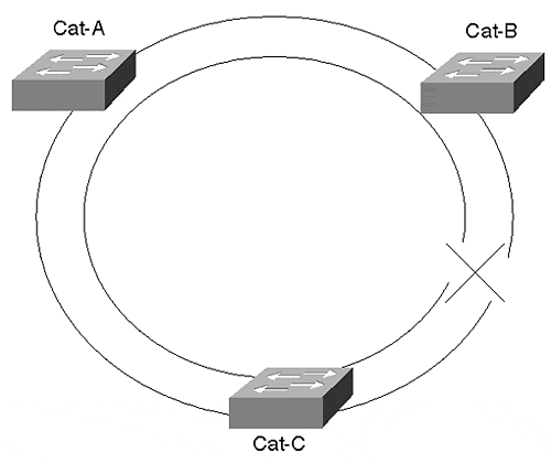
FDDI probably has the quickest failover rate because its resiliency operates at Layer 1, the physical layer. FDDI operates in a dual counter-rotating ring topology. Each ring runs in the opposite direction of the other ring. If a cable breaks between Cat-A and Cat-B as in Figure 8-17, both Catalysts see the loss of optical signal and enter into a wrapped state. Data continues to flow between all components in the network in spite of the cable outage. The cutover time is extremely fast because failure detection and recovery occur at Layer 1.
Figure 8-17. FDDI Resiliency

ATM Resiliency
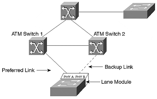
ATM also provides physical layer recovery. However, the failover time is longer than for FDDI. In an ATM network, a cable or interface failure can occur at the Catalyst or between ATM switches. If the failure occurs between ATM switches, the Catalyst requests the ATM network to re-establish a connection to the destination client(s). The ATM network attempts to find an alternate path to complete the connection request. This happens automatically. Figure 8-18 shows a Catalyst attached to two ATM switches for redundancy. One link, the preferred link, is the active connection. The second link serves as a backup and is inactive. Traffic only passes over the active link.
Figure 8-18. Catalyst ATM Resiliency

A failure can occur at the Catalyst. To account for this, the Catalyst LANE module provides two physical interfaces, PHY A and PHY B. In Figure 8-18, a Catalyst attaches to two ATM switches. PHY A attaches to ATM Switch 1 and PHY B attaches to ATM Switch 2. The Catalyst activates only one of the interfaces at a time. The other simply provides a backup path. If the active link fails, the Catalyst activates the backup port. The Catalyst must rejoin the ELAN and then reattach to the other client(s) in the network. Although ATM connections can establish quickly, the additional complexity increases the failover time as compared to FDDI links. The actual failover time varies depending upon the tasks that the ATM switches are performing when the Catalyst requests a connection to the ELAN or to another client.
Other types of failures can also occur in a LANE environment. For example, various server functions must be enabled for LANE to function. The LANE version 1 standard provides for only one of the servers in each ELAN. If these servers fail, it disables the ELAN. Cisco has a protocol called Simple Server Redundancy Protocol (SSRP) that enables backup servers so that the LANE can remain functional in the event of a server failure. This is discussed in more detail in Chapter 9, "Trunking with LAN Emulation."
Ethernet Resiliency
Ethernet options (both Fast Ethernet and Gigabit Ethernet) rely upon Spanning Tree for resiliency. Spanning Tree, discussed in Chapter 6, "Understanding Spanning Tree," operates at Layer 2, the data link layer. Components detect failures when they fail to receive BPDUs from the Root Bridge. Spanning Tree recovery can take as much as 50 seconds depending upon at what values you set the timers.
EtherChannel, both Fast and Gigabit, provide local resiliency. Figure 8-19 shows two Catalysts interconnected with an EtherChannel.
Figure 8-19. EtherChannel Resiliency

An EtherChannel has more than one link actively carrying data. If one of the links in Figure 8-19 fails, the remaining link(s) continue to carry the load, although with a reduced aggregate bandwidth. This happens without triggering any Spanning Tree events. Therefore, Spanning Tree times do not get involved. Failover for EtherChannel occurs quickly, because it uses Layer 1 failure detection and recovery. If you implement redundant EtherChannels, Spanning Tree activation times must be anticipated.
Resiliency: Failover Mechanisms
One final thought on resiliency. Many network engineers pride themselves in their forethought regarding failover mechanisms. They implement redundant interfaces, taking into account bandwidth planning in failover configurations. They even plan redundant power supplies. And yet they fail to recognize two particular failure modes: power source failures and cable plant routing. Although the redundant supplies can take care of internal equipment supply failures, to be fully protected, the redundant supplies should be attached to alternate sources on different circuit breakers in the facility. If both supplies attach to the same source and that source fails, the whole unit becomes dysfunctional. Place them on redundant sources!
An even more egregious error concerns cable paths. Although you can deploy redundant cable segments, make sure the segments take diverse paths! For example, if you deploy EtherChannel between Catalysts and the cable bundle is cut, the EtherChannel cannot carry data. The electrons fall on the floor. To provide full resiliency, use cable segments from different bundles, through different cable trays and patch panels, through different risers and conduits. Otherwise, if they are all in the same bundle, you are likely to lose the whole connection. Bundles get cut, not individual wires.
Bandwidth Requirements
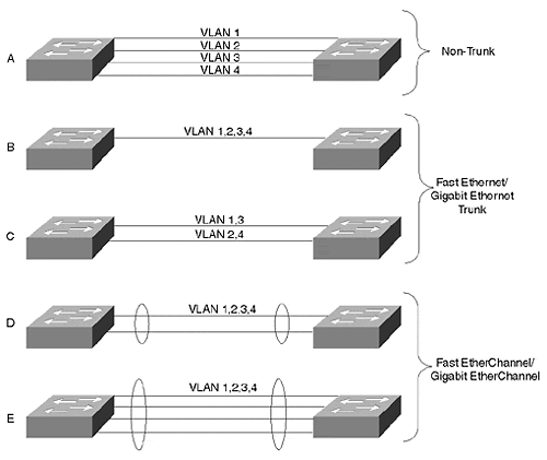
Right or wrong, network engineers most often use bandwidth capabilities for selecting a trunk technology. Catalyst offers a spectrum of options ranging from half-duplex FDDI through full-duplex Gigabit EtherChannel. Figure 8-20 illustrates a number of Fast Ethernet and Fast EtherChannel options with increasing bandwidth.
Figure 8-20. Bandwidth Options for Ethernet-Based Trunks

Part A of Figure 8-20 shows an interconnection where each link is dedicated to a VLAN. No trunk encapsulation is used and frames are transported in their native format. Only one link per VLAN between the Catalysts can be active at any time. Spanning Tree disables any additional links. Therefore, bandwidth options are only 10/100/1000 Mbps.
By enabling ISL trunking, you can share the link bandwidth with multiple VLANs. A single Fast Ethernet or Gigabit Ethernet link as in Part B of Figure 8-20 offers 100 or 1000 Mbps bandwidth with no resiliency. Running multiple trunks in parallel provides additional bandwidth and resiliency. However, VLAN traffic from any single VLAN can only use one path while the other path serves as a backup. For example, in Part C of Figure 8-20, two links run between the Catalysts. One link carries the traffic for VLANs 1 and 3, and the other link carries the traffic for VLANs 2 and 4. Each serves as a Spanning Tree backup for the other. This provides more bandwidth than in Part B of Figure 8-20 by having fewer VLANs contend for the bandwidth while providing another level of resiliency. However, each VLAN can still have no more than 100 or 1000 Mbps of bandwidth, depending upon whether the link is Fast Ethernet or a Gigabit Ethernet.
On the other hand, the VLANs in Parts D and E of Figure 8-20 share the aggregate bandwidth of the links. These links use Fast or Gigabit EtherChannel. With a two-port EtherChannel, the VLANs share a 400/4000 Mbps bandwidth. (Each link is full duplex.) A four-port version has 800/8000 Mbps bandwidth.
Table 8-8 compares the various interconnection modes providing a summary of the bandwidth capabilities, resiliency modes, and encapsulation types.
Table 8-8. A Comparison of Different Trunk Modes
Trunk Mode
Bandwidth (Mbps)
Resiliency
Encapsulation
Comments
Per VLAN link
Dedicated per VLAN 10/100/1000
Spanning Tree
None
VLANs traffic dedicated per link.
Ethernet
Shared 100/1000
Spanning Tree
ISL/802.1Q
Bandwidth reflects half duplex. Full duplex doubles bandwidth.
EtherChannel
Shared 200/400/2000/8000
Layer 1
ISL/802.1Q
Spanning Tree might activate in some cases.
FDDI
Shared 100
Layer 1 wrap
802.10
ATM
Shared 155/622
Layer 1 Diverse path
LANE/MPOA
Resiliency against network and local failures.
EAN: N/A
Pages: 223