14.2 CLASS DIAGRAM
|
14.2 CLASS DIAGRAM
Use cases and use case diagrams must at some point be translated into classes for eventual implementation. In UML, a class is represented by a rectangular box which in its most detailed representation is divided into three parts vertically. The name of the class is written in the uppermost partition of the box, followed by the class data members (called attributes in the parlance of UML) in the middle partition, followed by its member functions or methods (called operations in UML) in the lowest partition. The name of the class is shown in bold for a concrete class, and in italics for an abstract class. Figure 14.2 shows an example of this representation for a class Employee.
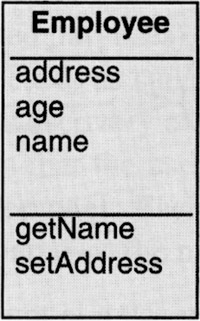
Figure 14.2
In its most common usage, a class diagram shows two relationships between different classes: generalization and association. A class C1 is a generalization of a class C2 if the former is a superclass of the latter. For example, the class diagram of Figure 14.3 shows with an arrowed solid line the class Employee as a superclass, and therefore a generalization, of the class Manager. Note that the generalization arrow, a closed triangle arrowhead, points to the superclass. An association, on the other hand, is depicted with a solid line between two classes, as between Employee and Corporation in the figure. You show an association link between two classes if the objects of one class must know about the objects of the other class in order to do their job.
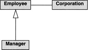
Figure 14.3
Other types of relationships between classes that can be depicted in a class diagram are aggregation and composition. The next two subsections discuss in greater detail the depiction of associations, aggregations, and generalizations in class diagrams.
In the OO literature, one also commonly sees mention of IsA and HasA relationships between classes. The former, as was mentioned in Chapter 3, represents a generalization-specialization sort of a relationship and the latter an association, an aggregation, or a composition. The name IsA is supposed to capture relationships such as
A Manager IsAn Employee A CorporateCustomer IsA Customer
In each such statement, what comes after IsA is a generalization or a super-type of what comes before (see Chapter 3 also). On the other hand, a statement like
An Order HasA Customer An Orchestra HasA Player A Window HasA Slider
expresses a containment, in the form of an association, an aggregation, or a composition.
We placed only the names of the classes in the boxes in the class diagram of Figure 14.3. How much detail one shows for a class depends on the perspective used in drawing the diagram. A class diagram may be drawn using three different perspectives: (i) conceptual, (ii) specification, and (iii) implementation
At the conceptual level, for each class you include only the bare minimum information needed to get an overall sense of the main concepts of a problem domain. This will most frequently be the diagram you would draw when you are just getting started with the design of an OO program. However, even after you have fully developed an OO system, a conceptual level diagram can be useful for communicating to others a coarse-level description of the system. At the specification level, you want to show the interfaces of each class. At this level you'd want to make explicit the class responsibilities, as embodied in the public operations for each class. At the implementation level, you want to show more precisely how a class was (or needs to be) implemented in code. Now you'd include the private and the protected attributes and operations as well.
14.2.1 Association as a Relationship Between Classes
The class diagram of Figure 14.3 showed an association to display the conceptual link between an object of type Employee and an object of type Corporation. An example of a more elaborate representation of such an association is shown in Figure 14.4. In the example depicted, an Employee has a data member called employedBy of type Corporation; this data member is shown as a label at the head of the arrowed association link from Employee to Corporation. We can talk about the label employedBy as the role played by a Corporation in an object of type Employee. The arrowhead on the association link from Employee to Corporation is referred to as the navigability arrow. The arrow tells us as to which of the two objects implements the association. In the example shown, the association with the rolename employedBy is implemented in the Employee class and therefore "belongs" to objects of type Employee. The label ‘0.1’ at the Corporation end of the association is referred to as the multiplicity of the association, which specifies how many objects of type Corporation in role employedBy may associate with a single object of type Employee. The multiplicity of ‘0..1’ means that an Employee is employed by no more than one Corporation.
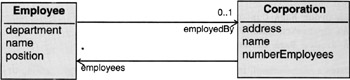
Figure 14.4
We can make similar remarks about the association link that goes from Corporation to Employee in Figure 14.4. The navigability arrow points towards the latter and the rolename label is employees with the multiplicity symbol ‘*’. This could be construed to mean that Corporation has a data member called employees of type Employee[]. The multiplicity of ‘*’ means that any number of employees, including zero, is allowed in an object of type Corporation. If there were a legal requirement that a Corporation possess at least one employee, with no constraints on the upper limit, the multiplicity label associated with the rolename employees would change to ‘1..*’. So the symbol ‘*’ in a multiplicity label means an indefinite number.
The two association links in Figure 14.4 can also be shown as a single line between the two classes. If we were to do so for our example, the line would show navigability arrows, rolenames, and multiplicity symbols at both ends. An association with no navigability arrows is considered bidirectional.
The association that was shown above is a binary association connecting two different classes. A binary association is also allowed to connect the same class to itself. Such an association link may connect two different objects from the same class, or one object to itself. In the latter case, the association would be called reflexive. Shown in Figure 14.5 is an example of an association that connects two different objects of the same class. This association would represent an Employee being allowed to supervise between 1 and 10 other employees.
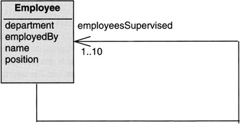
Figure 14.5
14.2.2 Aggregation and Composition as Relationships Between Classes
The objects participating in an association will often have independent, and, in some sense, equal existences of their own. But that is not true of all interclass relationships. In other relationships, especially those that relate a "whole" to its "parts," there can be lifetime dependencies between the whole and its parts. When the whole ceases to exist, the parts may get destroyed at the same time. A composition represents such a tight linkage between a whole and its parts.
Consider the example shown in Figure 14.6 where we have used filled diamonds to show compositions. Obviously, the "parts" that form the compositions, such as sliders, scrollbars, and so on, will cease to exist when a Window ceases to exist:
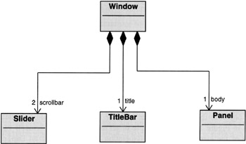
Figure 14.6
When you have a whole-part relationship in which the parts can have lifetimes independent of the whole, you have an aggregation. In the aggregation depicted in Figure 14.7, the performers would continue to exist even after the Orchestra object ceased to exist. As shown, a hollow diamond is attached to the class that is an aggregate. While, of course, this type of a relationship could also be captured by a straightforward association with appropriate multiplicities, the concept of an aggregation is supposed to capture the fact that an orchestra is the sum total of its performers and has no existence but for the conjoint existence of its performers.
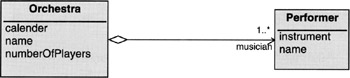
Figure 14.7
14.2.3 Representing Attributes
As mentioned before, the class data members—known as attributes in UML—are shown in a separate partition below the classname partition of the class box. The UML convention for displaying an attribute is:
visibility name [N] : type = initialValue {property-string} ---------------- where the visibility is one of
+ for public visibility for protected visibility - for private visibility
although the keywords public, protected, and private can also be used. The absence of a visibility marker indicates that the visibility is not shown (not that it is undefined or public). In the notation shown above, the name of the attribute is the string name. The symbol N inside square brackets denotes the multiplicity allowed for the attribute. A language-dependent specification of the implementation type of the attribute is denoted by type. The string initialValue is a language-dependent expression for the default value of the attribute for a newly created instance of the class, and property-string a string for expressing those traits of the attribute that are not captured by the rest of the syntax. For example, for an attribute that is read-only (such as a const in C++ or a final in Java), the property-string would be set to frozen. The convention for expressing multiplicity is the same as for an association. For example, if an attribute is allowed to take two or more values, the multiplicity symbol N would be replaced by ‘2..*’. The absence of multiplicity designation means that exactly one value is allowed for the attribute.
The underscore, shown under name and type, if used, signifies that the attribute has class scope, which means the same thing that it is static or one per-class, as opposed to one per object. Except for the name, all other elements of the syntax specification are optional.
14.2.4 Representing Operations
The third partition from the top, when it exists, of a class box shows its operations, meaning the member functions of the class. When a class is drawn at the specification level, only the public operations of the class are displayed. However, at the implementation level, you'd also want to show the private and the protected operations. The full UML syntax for an operation is
visibility name (parameter-list) : return-type {property-string} ----------------------------------- where visibility and name mean the same as for the case of attributes. The parameter-list is a comma-separated list of formal parameters, each specified using the syntax
kind name : type = defaultValue
where kind can be in, out, or inout, where in is for a parameter that passes a value to the operation, out for a parameter that fetches a value from the operation, and inout for a parameter that can play both roles. The symbols name, type, and defaultValue serve their usual roles
Back to the syntax for an operation, the symbol return-type is an implementation dependent language type of the value returned by the operation. The property-string can be used to express such traits as to whether an operation is abstract, which is the case when only the header is defined for the class and no implementation code is provided. Finally, operations that have class scope are underlined as shown above.
It is useful to make a distinction between two types of operations: query and modifier. A query operation simply tries to get the value of some class attribute without changing the state of the object. On the other hand, a modifier operation will change the state of the object.
14.2.5 Stereotypes
UML also allows a stereotype to be specified for a class just above the class name. The stereotype indicates what ‘kind’ of a class it is. The stereotype is enclosed in guillemots or the pair ‘<< >>,’ as in Figure 14.8. The diagram of Figure 14.8 tells us that the class Marginaccount is a class that belongs to the category financial instruments.
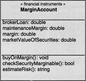
Figure 14.8
An abstract class is represented in the same way as the class shown above, except that the name of the class is in bold italics.
If it is necessary to show specific objects pictorially, the notation used is the same as for a class, except that now the object name is followed by the class name after a colon, the whole construct underlined, as shown in Figure 14.9.
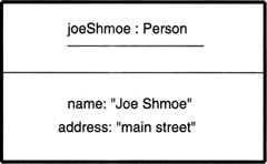
Figure 14.9
|
EAN: 2147483647
Pages: 273