14.1 USE CASE DIAGRAM
|
14.1 USE CASE DIAGRAM
In the context of OO design, a use case represents a single interaction between a human and the software system. It can also represent an interaction between another software package and the software under development. The set of all use cases describes the overall functionality of a software system. Since software is written to serve some purpose (or a set of related purposes), one of the first things you do in OO design is to list as many of the use cases as can be envisioned and to then represent them diagrammatically with UML. Discovery of the different use cases is facilitated by first listing all the different roles that the users (or other systems) can play with respect to the software under development. Each interaction with the system that is engaged in by each role is given a name—the name of the use case.
Figure 14.1 could be a first attempt at a use—case diagram for an internet auction system. This diagram shows three roles—Seller, Buyer, and Auction Server—each played by an actor. The use cases carried out by the actors through their designated roles are shown in ovals. Note that actors don't need to be human. In fact, one of the actors shown in the figure—Auction Server—is a software system. The link between an actor and a use case is referred to as a communication association, or just communication.
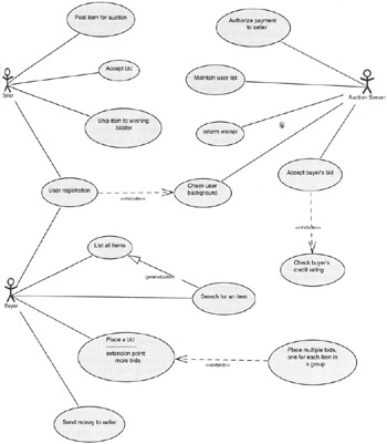
Figure 14.1
Use cases can have relationships between them. Figure 14.1 shows extend, include, and generalization relationships between the use cases. The extend relationship, shown with an arrowed, dashed line labeled <<extend>>,tells usthat the use case at the tail of the line is a variation on the use case at itshead. For example, the process of placing multiple bids simultaneously for a group of items offered by the same seller is a variation on the process of placing a single bid on a single item. The use case being extended can also display extension points to make explicit the condition under whichthe variant use case is to be invoked. The include relationship, shown with an arrowed, dashed line that is labeled <<include>>,tells us that the use case at the tail of the line needs to call on the use case at the head of the line for meeting its functional specification. For example, before a bid from a buyer can be accepted, a credit check must be run on the buyer. The generalization relationship, shown as a solid line with a closed triangle for an arrowhead, tells us that the use case at the head of the line is a more general casethan the use case at the tail of the line, implying that the use case at the tail of the line only needs to implement some more specialized logic to meet its functional requirements.
|
EAN: 2147483647
Pages: 273