2.9 The ATM Cell Header
2.9 The ATM Cell Header
The structure of the ATM cell is identical in both public and private ATM networks, with Figure 2.19 illustrating the fields within the five-byte cell header. As we will soon note, although the cell header fields are identical throughout an ATM network, the use of certain fields depends on the interface or the presence or absence of data being transmitted by an endpoint.
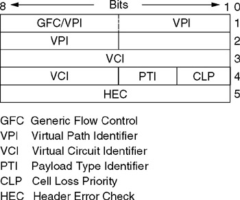
Figure 2.19: The ATM Header
2.9.1 Generic Flow Control Field
The Generic Flow Control (GFC) field consists of the first four bits of the first byte of the ATM cell header. This field is used to control the flow of traffic across the user -to-network interface (UNI) and is used only at the UNI. When cells are transmitted between switches, the four bits become an extension of the Virtual Path Identifier (VPI) field, permitting a larger VPI value to be carried in the cell header.
2.9.2 Virtual Path Identifier Field
The Virtual Path Identifier (VPI) identifies a path between two locations in an ATM network that provides transportation for a group of virtual channels, where a virtual channel represents a connection between two communicating ATM devices. When an endpoint has no data to transmit, the VPI field is set to all zeros to indicate an idle condition. As previously explained, when transmission occurs between switches, the GFC field is used to support an extended VPI value.
2.9.3 Virtual Channel Identifier Field
The Virtual Channel Identifier (VCI) can be considered to represent the second part of the two-level routing hierarchy used by ATM, where a group of virtual channels are used to form a virtual path.
Figure 2.20 illustrates the relationship between virtual paths and virtual channels. Here, the virtual channel represents a connection between two communicating ATM entities, such as an endpoint to a central office switch, or between two switches. The virtual channel (VC) can represent a single ATM link or a concatenation of two or more links, with communications on the channel occurring in cell sequence order at a predefined quality of service. In comparison, each virtual path (VP) represents a group of VCs transported between two points that can flow over one or more ATM links. Although VCs are associated with a VP, they are neither unbundled nor processed . Thus, the purpose of a VP is to provide a mechanism for bundling traffic routed toward the same destination. This technique enables switches to examine the VPI field within the cell header to make a decision concerning the relaying of the cell instead of having to examine the entire three-byte address formed by the VPI and the VCI. When an endpoint is in an idle condition, the VPI field is set to all zeros. Although the VCI field will also be set to all zeros to indicate the idle condition, other non-zero VCI values are reserved for use with a VPI zero value to indicate certain predefined conditions.
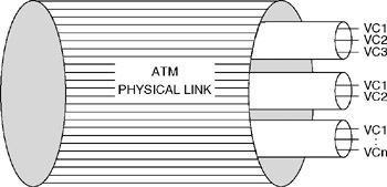
Figure 2.20: Relationship between Virtual Paths and Virtual Channels
As noted later, all VPIs and VCIs have only local significance on a particular connection between an endpoint and a switch or between two switches. At each switch in an ATM network, VPIs and VCIs can be remapped to different VPIs and VCIs. The actual route through an ATM network is established by signaling packets that are transmitted on a "well-known virtual channel," VPI = 0, VCI = 5.
2.9.4 Payload Type Identifier Field
The Payload Type Identifier (PTI) field consists of three bits in the fourth byte of the cell header. This field is used to identify the type of information carried by the cell. Values 0 through 3 are reserved to identify various types of user data, 4 and 5 denote management information, while 6 and 7 are reserved for future use.
2.9.5 Cell Loss Priority Field
The last bit in the fourth byte of the cell header represents the Cell Loss Priority (CLP) field. This bit is set by the AAL layer and used by the ATM layer throughout an ATM network as an indicator of the importance of the cell. If the CLP is set to 1, it indicates the cell can be discarded by a switch experiencing congestion. If the cell should not be discarded due to the necessity to support a predefined quality of service, the AAL layer will set the CLP bit to 0. The CLP bit can also be set by the ATM layer if a connection exceeds the quality-of-service level agreed to during the initial communications handshaking process when setup information is exchanged. For example, assume during the establishment of a VP/VC that the user and network agree upon the bandwidth and other QoS parameters. If the user's traffic violates the expected patterns, the CLP bit can be set to indicate that the cell is eligible for discarding .
2.9.6 Header Error Check Field
The last byte in the ATM cell header is the Header Error Check (HEC) field. The purpose of the HEC is to provide protection for the first four bytes of the cell header against the misdelivery of cells due to errors affecting the addresses within the header. To accomplish this, the HEC functions as an error detecting and correcting code. The HEC is capable of detecting all single and certain multiple bit errors as well as correcting single bit errors.
EAN: 2147483647
Pages: 111