Defining Network Topology
3 4
The place to start when diagramming a network is with the physical topology. Both Visio Standard and Visio Professional include shapes for linear (straight) bus, star, star-wired (token ring), dual ring (FDDI), and linear bus Ethernet topologies. The topology shapes all work in a similar manner. You drop them on the drawing page first. Then you add the nodes you want to display and drag them into approximate position around the topology shape. To connect them, drag a yellow control handle from the topology shape and glue it to a blue connection point on another shape, as Figure 14-4 shows. The handle turns red when it's glued.
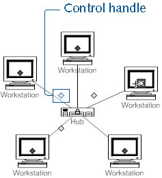
Figure 14-4. To connect nodes to a network, drag a yellow control handle from the topology shape to a connection point on the node. When you point to a control handle, the pointer changes to a four-way arrow to show that you can drag it.
Depending on the version of Visio that you have, topology shapes are located on the Basic Network Shapes, Basic Network Shapes 3D, or Logical Symbols stencils.
Tip
To quickly open a stencil, click the drop-down list arrow on the Open Stencil button on the Standard toolbar, choose Network, and then select the name of the stencil you want.
InsideOut
The Logical Symbols stencil in Visio Professional includes shapes that appear to duplicate shapes on the Basic Network Shapes stencil. The Bus, Ethernet, FDDI Ring, Star, and Token Ring shapes closely resemble their counterparts on the Basic Network Shapes stencil. The difference is that the Logical Symbols shapes are specifically designed to work in a scaled drawing page, although they also work on an unscaled page.
Attaching Nodes and Devices
Network shapes are designed to connect and stay connected as you drag them around the drawing page. They stay connected because glue keeps them that way. It's possible (and quite common) to drag connecting lines without gluing them. Usually, they look fine on the page and print as expected. However, it doesn't take any longer to glue shapes, and it certainly makes them easier to rearrange later. For example, when you move a workstation shape that's glued to a topology shape, the connecting line moves as well—and stays connected. Figure 14-5 shows how to glue shapes together.
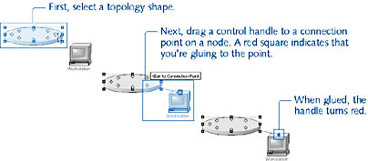
Figure 14-5. Visio tells you when you're gluing shapes; a red square around a point shows that the line will be glued to the point. In addition, a ScreenTip appears when you position the mouse over a point that you can glue to.
What if you want to attach more than eight nodes to a topology shape? All the topology shapes include eight control handles. The quick and dirty way to get more connections is to drag a second topology shape on top of the first one, and then use the second shape to connect more nodes. You should do this only after you have connected the first topology shape to its devices. A downside of this method is that your diagram now includes two shapes that in reality represent only one bus or ring, and if you generate reports based on the diagram, you could get inaccurate results.
InsideOut
You can add connection points to shapes and then draw lines between the points. To add a connection point, select the Connection Point tool on the Standard toolbar, press the Ctrl key, and then click to add a point. It helps to zoom in as you do this.
Drawing Network Connections
There are a couple of different ways to represent connections, such as the coaxial or fiber-optic cable between devices in a network. You can always draw them using the Line tool or Pencil tool, which is a quick way to represent network connections. To draw connections, click the tool you want on the Standard toolbar, and then draw from a connection point on one shape to a connection point on another. If you connect shapes this way, you won't be able to represent the connections in any reports that you create for the diagram, unless you add custom properties to the lines.
Visio also includes several shapes that you can use to connect network nodes, as Figure 14-6 shows. The shapes are designed to provide different routing behaviors and other attributes that you don't get by drawing connections with the Line tool.
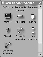
Figure 14-6. You can connect devices in a network using these and other connector shapes, which appear on both the Basic Network Shapes and Logical Symbols stencils.
The Basic Network Shapes stencil contains a variety of connecting shapes. Here are some of your connecting options:
- Use the Dynamic Connector. This shape is useful if you're showing a multitude of devices and want Visio to lay them out automatically for you. It appears on the Basic Network Shapes and Logical Symbols stencils. This shape has the same effect as using the Connector tool. After you connect shapes with the Dynamic Connector, use the Lay Out Shapes command on the Shape menu for automatic layout and routing. The best advice for using the Lay Out Shapes command is to remember that the results can be undone by pressing Ctrl+Z. Then you can try different settings to see which provides the best results.
For details, see "Laying Out Shapes Automatically."
Tip
The Dynamic Connector shape does not include custom properties, so if you're creating reports based on your diagram's contents, connections created with this tool won't be included. - Use the Connector tool. In a large network, it might be quickest to start with the nodes, and then connect them with the Connector tool on the Standard toolbar. You can also select the Connector tool and then drag shapes from stencils onto the drawing page. The shapes will be added with connections between them.
- Use connector shapes. Other connector shapes (Line Connector, Line-Curve Connector, and, in Visio Professional, Network Connector) work with the Lay Out Shapes command. If you drag a connector shape from the Basic Network Shapes stencil, it doesn't have custom properties. If you drag the shape from the Logical Symbols stencil, it does.
- Use the Comm-Link shape. The Comm-Link shape uses the common lightening bolt notation for indicating a link to a satellite, microwave tower, the Internet, and so on. It includes custom properties for tracking manufacturer, asset number, and more. Similar shapes are repeated on several stencils (Basic Network Shapes, Basic Network Shapes 3D, and Logical Symbols). They differ in fill color and the number of custom properties.

If you're using the Connector tool, the Dynamic Connector shape, or one of the line connector shapes to draw lines between network shapes, you might want to review the information about connections and glue in Chapter 3. This is particularly good advice if you're hoping to take advantage of the Lay Out Shapes command, which is powerful but can have unpredictable results.
For details about connector shapes, see "Adding Connectors to Your Diagrams."
Using Layers to Represent Different Networks
When you start a diagram with the Basic Network Shapes template, Visio sets up a drawing page automatically that includes layers you can use to organize shapes. You may not think this is particularly useful, but if, for example, you want to see alternative views of your network based on manufacturer, you can work with layers to do so. By default, Visio creates several manufacturer-specific layers as well as the Network and Connector layers.
As you drag shapes from the network stencils onto the page, they are added to the Network or Connector layer. You can choose to add shapes to the manufacturer-specific layers, and you can create new layers. Layers, however, are stored with a drawing page, not with a shape. If you insert a new page, it does not include the manufacturer layers. It might include the Network or Connector layer, however, which is added to the page when you add a shape that's assigned to that layer. Confusing? Perhaps, but the bottom line is that layers are useful for hiding and showing parts of a network or for selectively printing shapes by manufacturer.
To see the layers that are already included with your network diagram, choose View, Layer Properties. The Layer Properties dialog box lists the layers that have been created for the current page, as Figure 14-7 shows.
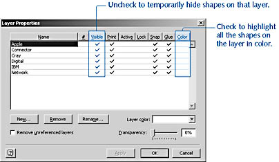
Figure 14-7. Visio assigns network shapes to layers by manufacturer, which allows you to work selectively with all the shapes assigned to a particular manufacturer.
For details about all the ways you can work with layers, see "Controlling Shapes with Layers."
The sections that follow summarize key information for working with layers in network diagrams.
Assigning a Network Shape to a Layer
To take advantage of the organizational possibilities that layers provide, shapes in a diagram must be assigned to a layer. Most network shapes are already assigned to either the Network or Connector layer. These assignments are maintained when you select a new layer assignment. That is, a shape can be assigned to more than one layer.
Follow these steps to assign a shape to a layer:
- Select a shape, and then choose Format, Layer.
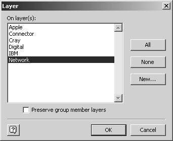
- In the On Layer(s) box, select the layer you want to assign the shape to. If you want to create a new layer for a manufacturer that isn't listed, click New, type the manufacturer name, and then click OK. Visio assigns the shape to the layer you selected.
- Click OK.
Viewing Shapes by Layer
You can view a list of the diagram's layers and the shapes assigned to each in the Drawing Explorer window. When you assign shapes to manufacturer layers, the Drawing Explorer provides a quick equipment list. Follow these steps to view a list of the diagram's layers:
- Choose View, Drawing Explorer Window.
- Double-click the Foreground Pages folder to see all the pages in your diagram.
- Double-click the page you're currently working on (or Page-1 if you haven't added or renamed any pages).
- Double-click the Layers folder.
If nothing happens, your drawing contains no layers. Otherwise, Visio lists all the layers on the page, as Figure 14-8 shows. If you expand a layer, you can see all the shapes assigned to it.
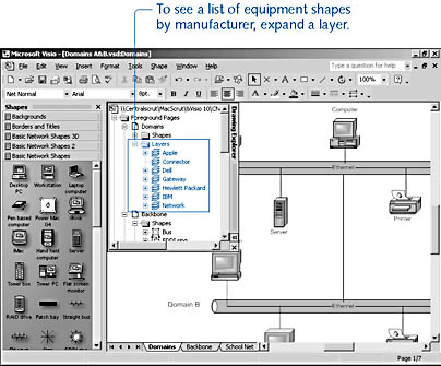
Figure 14-8. The Drawing Explorer window lists all the layers on a page and all the shapes assigned to a particular layer.
Tip
Right-click a layer in the Drawing Explorer window to display a shortcut menu with options.
Numbering the Shapes in a Network Diagram
You can keep track of equipment in a network diagram by assigning numbers to shapes. Visio can automatically number shapes, as Figure 14-9 shows, and provide you with options for the style of the number. You can also specify numbering options before you add shapes to the drawing page. That way, they'll be numbered automatically as you add them.
Tip
You can switch automatic shape numbering on and off by choosing Shape, Actions, Number Shape On Drop. This command is available only after you have used the Number Shapes command and if no shapes are selected.
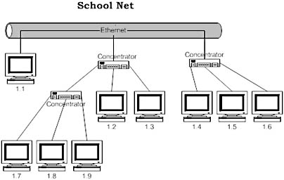
Figure 14-9. You can automatically number devices, nodes, or other shapes in your network diagram.
The Number Shapes command gives you several numbering options. You can
- Number all the shapes in the network diagram sequentially.
- Select a set of shapes, and then have Visio number them sequentially.
- Display a numbering tool on the screen, which lets you add and number shapes in your network diagram as you work.
- Specify a numbering style that automatically numbers each new shape you add to the diagram.
Visio numbers the shapes in the order you specify. If you don't specify an order, shapes are numbered from left to right and top to bottom. You can choose a different order, however, including back to front, which is based on the shape's stacking order (the order in which you dropped them on the page), or the order in which you select them.
To number shapes, follow these steps:
- Select the shapes you want to number, or cancel all selections to number all the shapes on the page.
- Choose Tools, Macros, Visio Extras, Number Shapes to display the Number Shapes dialog box, as Figure 14-10 shows.
- Choose the shape numbering options you want:
- Under Operation, choose whether to number shapes manually or automatically. The option you choose here determines the options that are available on the Advanced tab.
- Under Number Assigned, choose the numbering style you want to use. Use the Preview box to verify that the numbers look the way you want.
- If you want the numbering sequence to include shapes you add to the page later, select the Continue Numbering Shapes As Dropped On Page check box.
- Click the Advanced tab, and then choose the following options:
- Under Place Number, indicate where the numbers should be placed with respect to the shape's existing text.
- Under Auto Numbering Sequence, select the order in which shapes are to be numbered. This option isn't available when you number shapes manually.
- Under Apply To Options, indicate whether to number shapes according to their layer assignment.
Tip
For a description of each option, click the Help button in the Number Shapes dialog box. - Click OK to number the shapes.
Tip
To number shapes on other pages of a multiple-page network diagram, display the page, and then repeat the procedure. Shape numbering can be applied to only one page at a time.
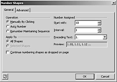
Figure 14-10. With the Number Shapes command, you can number devices sequentially as you add them or after you add them.
EAN: 2147483647
Pages: 211