Motherboard Connectors
| There are a variety of connectors on a modern motherboard. Figure 4.49 shows connector locations on a typical motherboard. Several of these connectors, such as power supply connectors, serial and parallel ports, and keyboard/mouse connectors, are covered in other chapters. Figure 4.49. Typical motherboard connectors.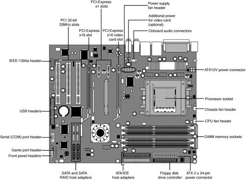 This section has figures and tables showing the configurations and pinouts of most of the other interface and I/O connectors you will find.
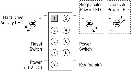
One of the biggest problems many people overlook when building and upgrading systems is the front panel connections. Connectors that don't match between the motherboard and chassis are one of the small but frustrating things that can be problematic in an otherwise smooth upgrade or system build. Having dependable standards for these connections would help, but unfortunately no official standard for the front panel connectors existed until October 2000, when Intel published the "Front Panel I/O Connectivity Design Guide." The latest version of this guide can be found, along with the motherboard form factor specifications, at www.formfactors.org. Before this standard was published, no official standard existed (and anarchy ruled). In addition, even though most chassis gave you individual tiny connectors for each function, some of the bigger system builders (for example, Dell, Gateway, MicronPC [now MPC], and so on) began using specialized inline or dual-row header connectors so they could build systems more quickly and efficiently. Coincidentally, most of those vendors used Intel boards, hence Intel's development of a standard. The front panel guide details a 10-pin keyed header connector for the main front panel switch/LED functions, as well as a 10-pin keyed USB header, a 10-pin keyed IEEE 1394 (FireWire/i.LINK) header, a 10-pin keyed audio header, and a 6-pin keyed IR header. The pinouts and configurations of these and other motherboard-based connectors are shown in the following figures and tables. Figure 4.50 details the front panel switch/LED header connector. Figure 4.50. Front panel switch/LED header connector. The pinout of the standard front panel switch/LED connector is shown in Table 4.56.
Some chassis provide a single 10-pin header connector for the front panel switch/LED connections, but most provide individual 2-pin connectors for the various functions. If 2-pin connectors are used, they are connected as shown in Figure 4.51. Figure 4.51. Standard front panel switch/LED connections using 2-pin connectors. The 2-pin connections to a standard 10-pin front panel switch/LED connector are shown in Table 4.57.
A chassis can use either a single-color or dual-color LED for the Power LED function. A dual-color LED can provide more information about the various power and message states the system might be in, including power on/off, sleep, and message-waiting indications. Table 4.58 shows the possible states and meanings for both single- and dual-color power LEDs.
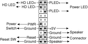
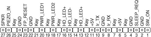
Many motherboards do not follow the industry-standard guidelines for front panel switch/LED connections, and many use alternative designs instead, one of which is shown in Figure 4.52. Figure 4.52. Alternative front panel switch/LED connector configuration. Some of Intel's older motherboards, as well as those made by other motherboard manufacturers, used a single-row pin header connector for the front panel connections, as shown in Figure 4.53. Figure 4.53. Alternative single-row front panel connector configuration. Table 4.59 shows the designations for the front panel motherboard connectors used on some motherboards.
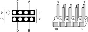
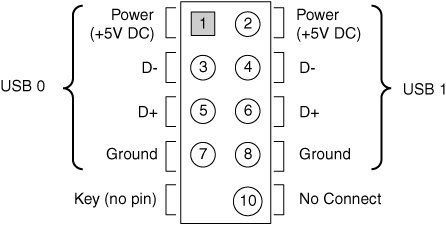
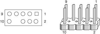
To adapt the connectors in your chassis to those on your motherboard, in some cases you might need to change the connector ends by removing the terminals and reinserting them into different positions. For example, I had a chassis that used a three-pin power LED connection, while the motherboard only had a two-pin connection. I had to remove one of the terminals, reinsert it into the middle position on the three-pin connector, and then plug the connector into the motherboard so that two pins were mated and the third empty position was hanging off the end of the connector. Fortunately, the terminals are easy to remove by merely lifting a latch on the side of the connector and then sliding the terminal and wire back out. When the terminal is inserted, the latch automatically grabs the terminal and locks it into position. Most motherboards include USB connectors, which are designed to be connected to front-mounted or rear bracket USB connectors in the chassis. The standard uses a single 10-pin keyed connector to provide two USB connections. The pinout of a standard dual USB motherboard header connector is shown in Figure 4.54 and Table 4.60. Figure 4.54. Dual-USB header connector configuration.
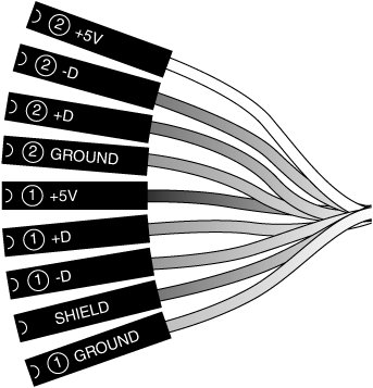
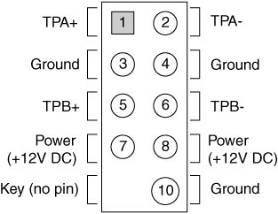
Many chassis includes multiple inline connectors for the dual-USBtofront panel or rear bracket connection, instead of a single keyed connector. An example of this is shown in Figure 4.55. Figure 4.55. Front panel USB cable using multiple individual non-keyed connectors. Using the multiple individual connectors shown in the previous figure, you would have to plug each individual connector into the proper pin. Some internal chassis USB cables use two 5-pin inline connectors, in which case you just need to ensure that you don't put them on backward. Consult your motherboard and chassis manual for more information if you are unsure about your particular connections. Caution If your chassis uses multiple individual non-keyed connections, you must be sure to connect them properly to the connector on the motherboard. If you connect them improperly, you can cause a short circuit to occur that can damage the motherboard or any USB peripherals you plug into the front panel connectors. Higher-quality motherboards usually have self-healing fuses on the power signals, which can prevent damage if such a situation occurs. Although IEEE 1394 (FireWire/i.LINK) is not found on most motherboards, some boards do incorporate this feature or offer it as an option. FireWire can also be added via an expansion card, and many of the cards have header connectors for front panel or rear bracket connections similar to that found on a motherboard. Figure 4.56 and Table 4.61 show the pinout of the industry-standard FireWire header connector. Figure 4.56. IEEE 1394 (FireWire/i.LINK) header connector configuration.
Note that the FireWire header connector has the same physical configuration and keying as a USB connector. This is unfortunate because it enables a USB front panel cable to be plugged into a FireWire connector, and vice versa. Either situation could cause a short circuit. Caution You must not plug a USB cable into a FireWire header connector, or a FireWire cable into a USB header connector. Doing so causes a short circuit that can damage the motherboard, as well as any peripherals you plug into the front panel connectors. Higher-quality motherboards usually have self-healing fuses on the power signals, which can prevent damage if such a situation occurs. Motherboards that have integrated audio hardware usually feature a front panel audio header connector. The pinout of the industry-standard front panel audio header connector is shown in Figure 4.57 and Table 4.62. Figure 4.57. Front panel audio header connector configuration.
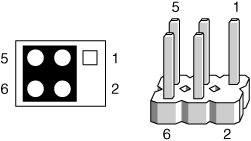
Some motherboards include an infrared data connector that connects to an infrared optical transceiver on the chassis front panel. This enables communicating via infrared to cell phones, PDAs, laptops, printers, or other IrDA devices. The industry-standard pinout for IrDA connections on a motherboard are shown in Figure 4.58 and Table 4.63. Figure 4.58. Infrared data front panel header connector configuration.
Other miscellaneous connectors might appear on motherboards as well; several are shown in Tables 4.644.72.
Note Some boards have a board-mounted piezo speaker. It is enabled by placing a jumper over pins 3 and 4, which routes the speaker output to the board-mounted speaker. Removing the jumper enables a conventional speaker to be plugged in. Most modern motherboards have three or four fan connectors for use with the processor fan, rear chassis fan, front chassis fan, and voltage regulator (power) fan (see Table 4.73). They all generally use the same 3-pin connector, with the third pin providing a tachometer signal for optional speed monitoring. If the motherboard is capable of monitoring the fan speed, it can sound an alarm when the fans begin to slow down due to bearing failure or wear. The alarm sound can vary, but it normally comes from the internal speaker and might be an ambulance sirentype sound.
Caution Do not place a jumper on this connector; serious board damage will result if the 12V is shorted to ground. | |||||||||||||||||||||||||||||||||||||||||||||||||||||||||||||||||||||||||||||||||||||||||||||||||||||||||||||||||||||||||||||||||||||||||||||||||||||||||||||||||||||||||||||||||||||||||||||||||||||||||||||||||||||||||||||||||||||||||||||||||||||||||||||||||||||||||||||||||||||||||||||||||||||||||||||||||||||||||||||||||||||||||||||||||||||||||||||||||||||||||||||||||||||||||||||||||||||||||||||||||||||||||||||||||||||||
EAN: 2147483647
Pages: 283