4.7 The User (U) Channel
| | ||
| | ||
| | ||
4.7 The User (U) Channel
The U bit of each subframe has a multiplicity of uses, many of which have remained hidden from the user of commercial equipment, such as the carrying of text, subcode, and other non-audio data. It is most widely used in consumer equipment and there is now a rather complicated AES standard for its use in professional applications (AES18, see below). There is also a Philips method for inserting data into the user channel, called ITTS (Interactive Text Transmission System), on which the CD system relies for the transferring of subcode and other non-audio data over the consumer interface. The U bit is only a single bit in each subframe, potentially allowing a user channel to accompany each audio channel, and its definition in the various standards is normally 'for any other information'. The user bits are not normally aggregated over the same block length as channel status data (192 subframes), although they may be, but are often aggregated over different block lengths depending on the application, or may simply be used as individual flags. Many devices, especially professional ones, do not use them at all, although this may change in the future.
In the following sections a number of the most common applications for user data are outlined, although the standards do not really prohibit users or manufacturers using this capacity for alternative purposes. AES3-1992 signals the use of the user bits in byte 1, bits 47 of channel status as shown in Table 4.1. IEC 60958 recommends a common format for the application of user bits, suggesting that the user bits in each subframe should be combined to make a single user bitstream for each interface.
| Bits 47 | User bits format |
|---|---|
| 0000 | Default, no user information |
| 0001 | 192-bit block structure |
| 0010 | AES18 |
| 0011 | User defined |
(It may be noted that the terminology used to describe the bit number of a message in the user channel can be confusing, depending on whether the message is considered as running 'MSB to LSB' or vice versa. We shall refer to the first transmitted bit of a message byte as 'bit 0', but some documents refer to this as 'bit 7'.)
4.7.1 HDLC Packet Scheme (AES18-1992)
Unlike channel status data, user data may consist of a wide variety of different message types, and the AES working group on 'labels' decided that the best approach to the problem for professional users was to allow the user channel to be handled in a 'free format', such that its maximum capacity of 48 Kbit/s could be shared between applications, with user data multiplexed into 'packets' of information which would share the interface. The history of this goes back to 1986, and a proposal by Roger Lagadec of Sony suggested that user data was very different to channel status data and would not suffer the same block structure, requiring a more flexible approach in which some messages could be sent once with minimal delay, whereas others might be repeated at regular time intervals, and yet others might have to be time-specific. It required that the data rate in the user channel be independent of the audio sampling rate, whereas the actual rate of user bits depends on the interface frame rate and thus on the sampling rate.
It is not necessary to document the whole history here, except to say that the direction of the work was influenced considerably by proposals from TDF (Tldiffusion de France) and others, well documented by Alain Komly 22 , suggesting the use of an asynchronous frame format already well established in the telecommunications and computer industries called HDLC (High-level Data Link Control). This is an internationally standardized way of transferring data at a bit-oriented level around networks (ISO 3309-2) 23 , and there are a number of commercial chips available which do the job of inserting data into the correct packet structure. The working group finally recommended a structure for carrying user data in AES18-1992 24 , and a useful commentary on this may be found in Nunn 25 . The AES18 standard was revised in 1996 26 to include recommendations for coding the data carried over the user channel. If this particular way of treating the user bits is implemented then it is indicated in byte 1 of the channel status information, bits 47, as shown in Table 4.1.
Although this is a flexible and versatile way of treating the user bit channel it is possibly overcomplicated for some applications, leaving it up to the user to build his or her own applications around the protocol. It treats the channel rather like a transport stream on an asynchronous computer network and is probably most well suited to large broadcasting installations and systems, although it may quickly be overtaken by protocols that use standard high speed computer networks for both audio and data communications. This approach is not part of the consumer format.
Among the key features of this standard are that the data rate of the user channel can be kept constant over a defined range of sampling rates (but only between 42 and 54 kHz in AES18), that a precise timing relationship can be maintained between audio and user data, that time-critical data may be transmitted within a specified and guaranteed period, and that the channel may be used simultaneously by a number of users. User data to be transmitted is formed into packets which are preceded by a header containing the address of the destination, and the packet is then inserted into the user data stream as soon as there is room. In order to ensure that the user data rate remains constant down to an audio sampling rate of 42kHz (which is 48kHz minus 12.5%) extra packing bits are added at the end of each block of packets which can be disposed of as the sampling frequency is lowered . At audio sampling rates below 42kHz the data rate will be lower, and thus some information would be lost if 48kHz data were to be sample rate converted to, say, 44.1 or 32kHz, but it is expected that some form of data management would be implemented to ensure that important data gets the highest priority in these circumstances.
Data is formatted at a number of levels before being transmitted over the interface, starting at the highest level the 'application level' and ending at the lowest level the 'physical level' at which the data is actually inserted bit by bit into the audio interface subframe structure. It is not intended to cover the process by which this is achieved here, since this would constitute needless repetition of available documentation. What is important is some commentary on the handling of different types of message, particularly time-specific messages, and on the insertion of additional messages at later points in the interface chain.
AES18 allows for the handling of time-specific messages by formatting the user data packets into blocks, normally of fixed but definable length, and repeating these at a user-definable rate which can be set to correspond to time intervals pertinent in the application concerned . An optional 'system packet' may also be transmitted at block intervals which may contain timecode data among other things, and sets priorities for different types of message which may have more or less urgency. It recommends some useful repetition rates of blocks, which correspond to the timing intervals of frames in audio and video applications, as shown in Table 4.2. In some applications variable block lengths may be necessary, such as when using 48 kHz audio with NTSC video (which runs at 29.97 fps) where there is not an integer number of audio samples per video frame.
| Blocks per second | Duration (ms) | Application |
|---|---|---|
| 24 | 41.67 | Film |
| 25 | 40 | PAL, SECAM video or 50 frame per second (fps) HDTV |
| 29.97 | 33.37 | NTSC video |
| 30 | 33.33 | 60 fps HDTV |
| 33.33 | 30 | DAT |
In order to allow for the insertion of messages of varying importance at different points in the system, the standard sets down comprehensive rules governing the way in which messages should be prioritized. The maximum delay involved in inserting a packet of data depends on its priority (from 0 to 3), and the block length involved. The highest priority packet (level 3) may be inserted once per block, and as the priority is decreased the packets are inserted only once per so many blocks. Since the shortest practical block length is 10 ms, this is the minimum delay one might anticipate.
The original version of the standard defined packet structures and transport stream protocols, but said little or nothing about the format or structure of messages. AES18-1996 describes a means of addressing for messages that defines the application area and purpose of the message. Examples include messages about programme description, engineering notebook and switching information. Collaboration is claimed with the EBU regarding the format and structure of such messages.
4.7.2 Consumer Applications of the User Bit
IEC 60958 is more specific about recommended protocol for the user bitstream than the original IEC 958, probably because the range of uses of the interface has grown greatly in the intervening period. In essence it suggests that the user bits for the two subframes should be combined to make a single data stream for the interface concerned. The basis for the recommended structure lies in the Compact Disc application of the user bits to transfer QW-channel subcode data, but it has been generalized to other product categories.
The relevant bits should be formed into information units (IUs) of eight bits, starting with a binary 1 and followed by seven information bits. Probably because of the historical link with CD subcode the eight bits of an IU are called the PW bits, although the P bit does not bear relationship to the P-channel subcode data on CD. IUs are typically separated by four '0' bits, but can be separated by between none and eight. More than eight '0' bits in a row signifies the start of a new message. An example is shown in the next section, relating to the CD.
Three classes of equipment are indicated, each with a different role in relation to user bits, being essentially those that originally generate user bits (Class I), those that pass them through or are 'transparent' to user bits (Class II), and mixed-mode equipment such as may combine signals or process them (Class III). In the case of Class II equipment that delays the audio signal it is recommended that the user bits are similarly delayed in order to preserve time alignment.
Because of the somewhat disorganized history of user bit application in consumer products, different categories of products (indicated by the category code in channel status) have their own message structures. However, there is now a general structure that is recommended for new products that can start from scratch in their implementation. In the general structure a message may be made up of a minimum of three and a maximum of 129 IUs, although messages of 96 IUs are reserved specifically for certain classes of laser products. The first three IUs have a specific function, as shown in Figure 4.10, indicating the type of message, the number of remaining IUs in the message (after the first three) and the category code of the originating equipment. Message data is then carried in successive IUs. Because of the complexity and number of possibilities for user bit messaging in consumer products, the reader is referred to the standard and its annexes for further details, although most of the annexes show relatively little in this respect.
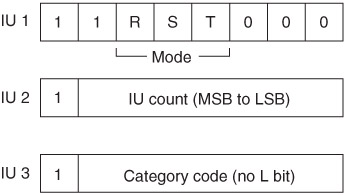
Figure 4.10: Format of the first three IUs of the consumer user bitstream.
4.7.3 Applications of the User Bit in Compact Disc and MiniDisc Systems
The following is given as a common example of the application of user bits in two consumer product categories. Compact Disc and MiniDisc players having consumer format digital outputs normally place subcode data in the user bits. This is in addition to the control bits of the Q-channel subcode from the disc which are transmitted within channel status (see section 4.8.9) and formed the only full specification for user bits implementation in the original IEC 958 document, as Annex A.
In this application the user bits for the left and right subframes are treated as one channel, and the Q to W subcode data is multiplexed between them (the P flag is not transmitted since it only represents positioning information for the transport). The subcode data block is built up over 1176 samples, formed into sync blocks of 12 samples each (making 98 subcode symbols, which include two symbols for block sync). There are eight subcode bits in each of these sync blocks (PW), but only seven of them are transmitted (QW) over the interface. Because the subcode data rate is lower than the user bit rate, zeros are used as packing between the groups of subcode bits. The number of zeros is variable, principally to allow for variable speed replay to 25%. As shown in Figure 4.11, the subcode block begins with a minimum of 16 zeros, followed by a start bit (a binary '1' which some documents call 'P' although this might be misleading since it is always a '1' and thus contains no additional information). There then follow seven subcode bits (Q1 to W1), after which there may be up to eight zeros before the next start bit and the next seven bits of subcode data. Only four packing zeros are shown in this diagram. This pattern is repeated 98 times, after which a new intermessage sync pattern of at least 16 zeros is expected.
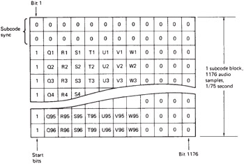
Figure 4.11: An example of user bits formatting in the CD system.
The Q data in the subcode stream can be used to identify track starts and ends, among other things (see the full CD specification in IEC 908), so it is useful when transferring CDs to DAT or vice versa (for professional purposes, of course), or from a CD player to a CD recorder, since the audio data and the track IDs are duplicated together and the copy is a true clone of the original. Between CD machines there is usually little problem in copying subcode data, since the two machines are of the same format, but between CD and DAT a special processor unit is normally required to convert DAT track IDs to CD track IDs or vice versa and there are occasional discrepancies. Since the P flag is not transferred over the interface the copy may only rely on Q subcode information and there is usually a gap between the start of the P flag on the CD and the Q subcode track number increment. Some CD players increment the track number on their own displays at the start of the P flag and then count down to the true track start using the Q data, whereas a copy of such a recording would only increment the track number at the true track start. There is also occasionally a small delay in the assertion of the track start flag on DAT recordings, due to the automatic start ID facility used in many machines which writes a new start ID when the audio level rises above a certain point, which may sometimes be compensated for in the transfer.
4.7.4 Applications of the User Bit in DAT Systems
As with the CD/MD, the consumer interface on DAT machines also carries some additional information in the user bits. The first edition of IEC 958 suggested that subcode data would be carried in the four auxiliary bits rather than the user bits but IEC 60958 now shows subcode in the user bits, with nothing in the aux bits. Considering the subcode information which could be sent in the user bits the actual implementation is incredibly crude, as it simply indicates the presence or lack of start and skip (shortening) IDs on the tape. This approach was in fact inherent in the DAT design standard right from the start 27 .
As shown in Figure 4.12, sync, start ID and skip ID are transmitted over the interface with relation to the DAT frame rate of 33.33 frames per second. As with CD, the user bits of the left and right channel subframes are considered together and (differently from the 'general' format described above) each 'message' consists of only one IU with only two active bits (Q and R). The sync ID (P bit) is transmitted once per frame by setting the user bit of the first left channel sample (L ) of that frame true this simply indicates where the frame begins and could be used for crude synchronization of two machines. (In other words, the user bit of the interface subframe corresponding to the first sample of the DAT frame is always set true.) When a start ID is present on the tape the user bit of the following interface subframe (which is the Q bit of the IU or the first right channel sample of the DAT frame, or R ) is also set true, and this lasts for 300 30 frames, or about 10 seconds (the same duration as the start ID information on the tape). When a skip ID is encountered in normal play mode (without actually skipping) the user bit of the next left channel subframe (the R bit or L 1 ) is set true, and this is repeated for 33 3 frames, or about 1 second. When the DAT machine is programmed to act on skip IDs it will skip to the next start ID, and in this case the user bit of the L 1 frame is set true only once in the first frame that it is encountered. All the other user bits are set to zero.
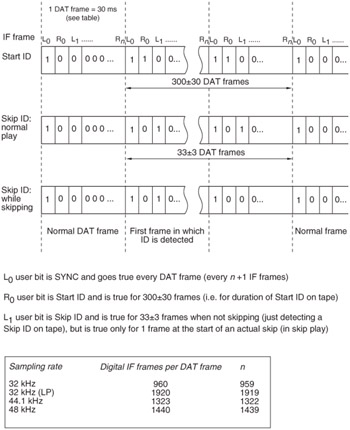
Figure 4.12: Signalling of DAT start and skip IDs in user bits (user bits only shown).
The number of samples corresponding to a DAT frame depend on the sampling rate, and therefore this dictates the distance between sync, start and skip IDs in the user bits of the interface. At 48 kHz there are 1440 left and right samples per frame, making 2880 subframes between the occurrence of these user bits. At 44.1 kHz this gap is reduced to 2646 words, and in the 32 kHz long play mode found on some players it is 3840 words.
| | ||
| | ||
| | ||
EAN: 2147483647
Pages: 120
- Structures, Processes and Relational Mechanisms for IT Governance
- Measuring and Managing E-Business Initiatives Through the Balanced Scorecard
- A View on Knowledge Management: Utilizing a Balanced Scorecard Methodology for Analyzing Knowledge Metrics
- Managing IT Functions
- The Evolution of IT Governance at NB Power