4.8 Channel Status Data
| | ||
| | ||
| | ||
4.8 Channel Status Data
Channel status data (represented by the C bit in each subframe) is commonly a problematic area with implementations of the standard two-channel interface. It is here that a number of incompatibilities arise between devices and it is here that the main differences exist between professional and consumer formats, because the usage of channel status in consumer and professional equipment is almost entirely different. In this section the principles of channel status usage will be explained, together with an introduction to potential problem areas, although discussion of practical situations is largely reserved until Chapter 7.
4.8.1 Format of Channel Status
Although there is only one channel status (C) bit in each subframe, these are aggregated over a period of time to form a large data word that contains information about the audio signal being transmitted. The two audio channels theoretically have independent channel status data, although commonly the information is identical, since most applications are for stereo audio. Starting with the frame containing the Z preamble, channel status bits are collected for 192 frames (called a channel status block), resulting in 192 channel status bits for each channel. This long word is subdivided into 24 bytes, each bit of which has a designated function, but the function of these bits depends on whether the application is consumer or professional. The channel status information is updated at block rate, which is 4 ms at a sampling rate of 48 kHz and longer pro rata at other sampling rates.
Standards such as AES3 only cover the professional application of channel status, but the EIAJ, IEC and British standards all include a section on consumer applications as well. In the early days of digital interfaces relatively little notice was taken of channel status data by some products and implementations could be sparse, leading to incompatibilities. In AES3 (1992) the format of professional channel status data was extended and explained more carefully , with the intention of setting down more clearly what devices should do with this data if they were to conform properly with the standard. Even more recently the amendments to AES3 have indicated yet further detail in channel status implementation to accommodate such things as new channel modes and higher sampling frequencies. These revisions should ensure that more recent professional devices are more compatible with each other, although it will not help the situation with older equipment. The problem of incompatibility in channel status data is covered further in Chapter 7.
4.8.2 Professional and Consumer Usage Compared
It is both a blessing and a curse that the formats of professional and consumer data are so similar. It is a blessing because the user may often wish to transfer material from one to the other and the similarity would appear to make this possible (see section 6.7), but it is a curse because the usage of channel status is so different between the two that the potential for problems is very high, due to the likely misinterpretation of this information by a receiver of the other format. (There is no technical reason, though, why a device should not be designed to interpret both formats correctly.) The first bit of the channel status block indicates whether the usage is consumer (0) or professional (1), and this bit should be interpreted strictly in order to avoid difficulties. (It should be noted that before the consumer format was standardized by the IEC the first bit of the consumer channel status data actually represented ' four-channel mode', not 'consumer/ professional'. Some early devices may still exhibit this feature.)
Figure 4.13 shows a graphical comparison of the beginnings of the channel status blocks in professional and consumer modes. Clearly bit 0 is the same and indicates the usage, and bit 1 is also the same, indicating linear PCM audio (0) or 'other purposes' (1) usage of the interface (such as data-compressed audio, as discussed in section 4.9), but here the similarity stops. In the professional version three bits (bits 2, 3 and 4) are used to signal pre-emphasis, but in the consumer version only two (bits 3 and 4) are used for emphasis indication in the linear PCM mode (although only one is actually used in practice). Bit 2 is used to signify copyright status in the consumer format. Already there is room for incompatibility since a professional device trying to interpret a consumer signal or vice versa could confuse copy protection states with emphasis states. Since copy protection is not normally an issue in professional applications, there is no provision for signalling it in the professional interface.
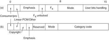
Figure 4.13: Comparison of (a) professional and (b) consumer channel status, bits 116.
It is clearly crucial to ensure that the first bit of channel status is correctly interpreted before any further interpretation of channel status takes place. Devices that ignore this fundamental difference in implementation, or that simply ignore most channel status information, may work adequately with other devices some of the time. It is, however, likely that the ever increasing number of possible device configurations will lead to communication difficulties if the channel status implementation is not interpreted strictly.
4.8.3 Professional Usage
Usage of Channel Status and Channel Modes
Figure 4.14 shows the format of the professional channel status block, and Figures 4.15 and 4.16 show the functions of the first (byte 0) and second (byte 1) bytes in more detail. These indicate basic things about the nature of the source, such as its sampling frequency (a root of problems, as discussed in section 6.7), its pre-emphasis, the mode of operation (mono, stereo, user defined, etc.) and the way in which the user bits are handled (see section 4.7 and Table 4.1). The sampling frequencies indicated in bits 67 of byte 0 are the original and basic ones. If one of the new rates is to be used, as now indicated in byte 4, the byte 0 indication can be set to 00 and the actual rate indicated in byte 4. Indication of the sampling frequency here is not, in any case, a requirement for operation of the interface. Recent versions of the standard use byte 1 to indicate that the interface is operating in single-channel-double-sampling-frequency mode, as discussed in section 4.4. In such a case the sampling frequency indicated in byte 0 is essentially the frame rate of the interface rather than the audio sampling frequency (which would be twice that).
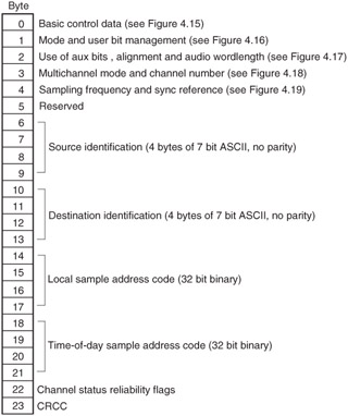
Figure 4.14: Overview of the professional channel status block.
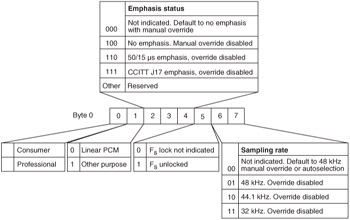
Figure 4.15: Format of byte 0 of professional channel status.
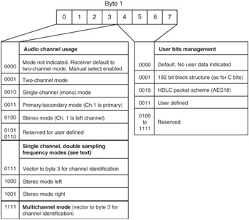
Figure 4.16: Format of byte 1 of professional channel status.
The EBU has made recommendations concerning the primary/secondary mode of the interface for broadcasting applications in document R72-1999 28 . This identifies three possible uses for the primary and secondary channels as shown in Table 4.3. The means by which these will be indicated elsewhere in channel status has not yet been formally agreed.
| Primary | Secondary |
|---|---|
| Complete monophonic mix | Reverse talkback |
| Mono signal (M) | Stereo difference signal (S) |
| Commentary | International sound |
Use of Aux Bits and Audio Resolution
Figure 4.17 shows how byte 2 is split up, with the first three bits describing the use of the auxiliary bits (see section 4.5), and Table 4.4 shows how bits 35 are used to indicate audio word length. In Amendment 4 to AES3-1992, bits 6 and 7 are used to indicate the audio alignment level as shown in Table 4.5. Byte 2 allows the source to indicate the number of bits actually used for audio resolution in the main part of the subframe. No matter what the audio resolution, the MSB of the audio sample should always be placed in the MSB position of the interface subframe. This allows receiving devices to adapt their signal processing to handle the incoming signal resolution appropriately, such as when a 16-bit device receives a 20-bit signal, perhaps redithering the audio at the appropriate level for the new resolution in order to avoid distortion. This byte was less comprehensively used in the original version of AES3, only indicating whether the audio word length was maximum 20 bits or 24 bits (in other words, whether the aux bits were available for other purposes or not).
| Bits states 3 4 5 | Audio word length (24-bit mode) | Audio word length (20-bit mode) |
|---|---|---|
| 0 0 0 | Not indicated | Not indicated |
| 0 0 1 | 23 bits | 19 bits |
| 0 1 0 | 22 bits | 18 bits |
| 0 1 1 | 21 bits | 17 bits |
| 1 0 0 | 20 bits | 16 bits |
| 1 0 1 | 24 bits | 20 bits |
| Bits 67 | Alignment level |
|---|---|
| 00 | Not indicated |
| 01 | -20 dB FS (SMPTE RP155) |
| 10 | -18.06 dB FS (EBU R68) |
| 11 | Reserved |
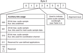
Figure 4.17: Format of byte 2 of professional channel status.
Multichannel Modes
Byte 3 is used to describe multichannel modes of the interface, as shown in Figure 4.18. Although the interface can only carry two channels, these may be specific channels of a bundle of associated signals carried over a group of interfaces. The use of the remaining bits depends on the state of bit 7, so that either the whole byte is used to denote the channel number or part of it is used to indicate a particular multichannel mode and the other part to indicate the channel number. The latter is likely to be used for applications like the signalling of particular surround sound configurations, as there are numerous ways in which numbered channels can be assigned to speaker locations (e.g. Left, Right, Centre, Left Surround, Right Surround) 29 .
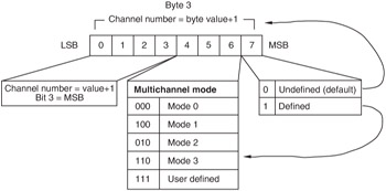
Figure 4.18: Format of byte 3 of professional channel status.
Sampling Frequency Status
Byte 4 is illustrated in Figure 4.19. The first two bits are used for indicating whether the signal can be used as a sampling frequency reference, according to the AES11 standard on synchronization. In the '00' state these bits indicate that the signal is not a reference, whilst the '01' state is used to represent a Grade 1 reference and the '10' state is used to represent a Grade 2 reference. This topic is discussed in greater detail in Chapter 6. Bits 36, in recent amendments, are now used to describe sampling frequencies not originally mentioned in the standard, as detailed in Table 4.6. These are audio sampling frequencies, not necessarily interface frame rates, so they are not dependent on the interface modes described in byte 1. Bit 7 is a sampling frequency scaling flag used to signify (in the '1' state) so-called 'drop-frame' or 'pull-down' frequencies of 1/1.001 times the basic frequency that sometimes arise in post-production operations when digital audio equipment is synchronized to NTSC television signals.
| Bits 63 (in that order) | Sampling frequency |
|---|---|
| 0000 | Not indicated (default) |
| 0001 | 24kHz |
| 0010 | 96kHz |
| 0011 | 196kHz |
| 1001 | 22.05kHz |
| 1010 | 88.2kHz |
| 1011 | 176.4kHz |
| 1111 | User defined |
| All other states | Reserved |
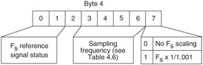
Figure 4.19: Format of byte 4 of professional channel status.
Source and Destination Identification
In bytes 6 to 13 it is possible to transmit information concerning the source and destination of the signal in the ASCII text format used widely in information technology (see ISO 646). ASCII characters are normally seven bits long (although extended character sets exist which use eight bits), and can represent alphanumeric information. The eighth bit is often used as a parity bit in telecommunications, but it is not used in this application, being set to zero. (AES3-1985 and IEC 958 specified odd parity, but this was changed in AES3-1992 to no parity.) Some ASCII characters are non-printing symbols called 'control characters' (the first 31 (hex 01-F) and the last one (hex 7F)) and these are not permitted in this application either. Using this part of channel status the user can 'stamp' the audio signal with a four-character label to indicate the name of the source (bytes 69), and the same for the destination (bytes 1013). It is possible to use destination labelling in automatic routers in order that a signal may control its own routing. The format for these ASCII messages is LSB first, and with the first character of each message in bytes 6 and 10 respectively.
Sample Address Codes
Bytes 1421 carry what are called 'sample address codes', which are a form of timecode but counting in audio samples rather than hours, minutes, seconds and frames. Bytes 1417 are a so-called 'local sample address' which can be used rather like a tape counter to indicate progress through a recording from an arbitrary start point, and bytes 1821 are a time-of-day code indicating the number of samples elapsed since midnight. Usually this is the time since the device was reset or turned on, because most devices do not have the facility for resetting the sample address code to time of day, but AES3-1992 contains a note to state that it should be the time of day which was laid down during the original source encoding of the signal, and should not be changed thereafter, implying that it should be derived from offtape timecode if that exists.
The four bytes for each sample address code are treated as a 32-bit number, with the LSB sent first; 32 bits allows for a day of 4 294 967 296 samples, which represents just over 24 hours at a sampling rate of 48 kHz. (At the maximum sampling frequency normally allowed for over the interface (54 kHz) 32 bits are not quite enough to represent a whole day's worth of samples, allowing a count of just over 22 hours, but this sampling frequency is normally only used as an upward varispeed of 48 kHz and thus is a non-real -time situation in any case.) If the sampling frequency is known then it is a straightforward matter to convert the sample address to a time of day. The sample address code is updated once per channel status block; thus it is incremented in steps of 4 ms at 48 kHz, and represents the sample address of the first sample of that block.
Byte 22 is used to indicate whether the data contained in certain channel status bytes is reliable, by setting the appropriate bit to '1' in the case of unreliable information, as shown in Table 4.7.
| Bits | Bytes reliable |
|---|---|
| 03 | Reserved |
| 4 | Bytes 05 |
| 5 | Bytes 613 |
| 6 | Bytes 1417 |
| 7 | Bytes 1821 |
The last byte of the channel status block (byte 23) is a CRC (Cyclic Redundancy Check) designed to detect errors in channel status information only , and a simple serial method of producing CRC information is given in AES3-1992. (Most modern AES/EBU interface chips generate channel status CRC automatically.) The CRC byte was not made mandatory in AES3-1985 and a number of systems have not implemented it, but in AES3-1992 it was made mandatory in the 'standard' implementation of the interface (although there is a 'minimum' mode in which it can be left out). The presence or lack of the CRC byte in different devices is a root of incompatibility in older equipment because devices expecting to see it may refuse to interpret channel status data which does not contain a CRC byte and will assume that it is always in error.
Any bits in channel status that are either not used or reserved should be set to the default state of binary '0' another important factor in ensuring compatibility between devices.
4.8.4 Levels of Professional Channel Status Implementation
AES3-1985 was rather unclear as to what manufacturers should do with channel status if they were not implementing certain features. Receivers could be found all the way between the two extremes of either interpreting the standard so literally that they expected to see every single bit set 'correctly' before they would work, or else interpreting it so loosely that virtually anything would work, often when it should not. (To be fair it is true that much of the time communication worked without a problem.) In the 1992 revision it was decided to recommend three levels of implementation at the transmitter end, encouraging manufacturers to state the level at which they were working. These levels have been called 'minimum', 'standard' and 'enhanced'. It is intended that at all levels the rest of the frame should be correctly encoded according to the standard.
At the minimum level channel status bits are all set to zero except for the first bit which should be set to signify professional usage. Such an implementation would allow 'belt and braces' communication in most cases, but leaves room for many problems since CRC is not included and neither is any indication of pre-emphasis or sampling frequency. It is intended in such a case that the receiver should set itself to the default conditions (48 kHz, no emphasis, two-channel mode) but allow manual override.
At the standard level the transmitter is expected to implement bytes 0 to 2 and 23 of channel status. This then allows for all the information about the source signal and use of different bits in the frame to be signalled, as well as including the CRC.
An enhanced mode is also allowed which is basically the standard data plus any additional data such as sample address and source identification.
As far as receivers are concerned there is currently little in the way of insistence in the standards concerning how receivers should behave in the case of certain data combinations, except that the manufacturer should state clearly the data recognized and the actions which will be taken. This situation is clarified in AES2-ID, in which a number of equipment classifications are specified, indicating the level to which the device processes and modifies channel status. Manufacturers should publish implementation charts for their devices, much as manufacturers of MIDI-controlled equipment publish such charts in operators' manuals, allowing users to identify the roots of any incompatibility. Such charts , examples of which are found in AES2-ID, should also indicate the treatment of the user bit and validity bit, as well as indicating supported sampling frequencies/ resolutions .
In AES2-ID, the implementation of channel status is grouped into A, B and C classes according to the sophistication and nature of the device. Group A devices behave like a wire, simply passing whatever they receive and not storing or acting on it in any way (e.g. a crosspoint switcher). Group B devices all do something with the data they receive, to varying degrees. B1 only decodes audio, not channel status (highly unlikely and possibly risky); B2 decodes channel status but does not store or pass it on; B3 stores and/or passes on channel status data indicated in the implementation chart, modifying it as necessary to reflect the correct state of the audio signal it accompanies . Group C is terminal end equipment (e.g. D/A convertor) that either does not decode channel status (C1) or does and acts on it as indicated (C2).
4.8.5 Overview of Channel Status in Consumer Applications
In a way the use of channel status is rather more complicated in consumer applications because of the many types of consumer device and the wide variety of data types that may be transmitted. The format of the basic block is shown in Figure 4.20 and a more detailed breakdown of the first byte (byte 0) is shown in Figure 4.21. (For a comparison with byte 0 of the professional format see Figure 4.15.) Bits 6 and 7 in the consumer format define the 'mode' of use of the channel status block, and so far only mode 0 is standardized with these bits set to '00'. There was a proposal for a mode 1 to be used for 'software information delivery', with the bits set to '10' respectively, in order to allow the transmission of information about production details on prerecorded media. This was written up as a technical report that appears listed as IEC 60958-2 (1994) but is not considered to be formally part of the standard.
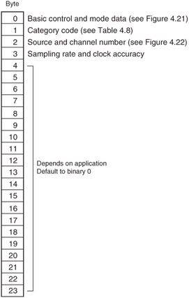
Figure 4.20: Overview of the consumer channel status block.
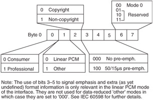
Figure 4.21: Format of byte 0 of consumer channel status.
The usage of channel status in consumer equipment depends on the mode, and also on the category code which defines the type of device transmitting the data in the second byte (byte 1) of channel status (see the next section). In mode 0, byte 2 of channel status is used to indicate a source number from 1 to 16 and a channel number (see Figure 4.22), so that in the case of sources with multiple audio channels it is possible to signal which two are being transmitted. Byte 3 is used to indicate the sampling frequency of the source and the clock accuracy of the source (see Table 4.8).
| Bits 2427 | Sampling frequency (kHz) |
|---|---|
| 0000 | 44.1 |
| 0001 | 88.2 |
| 0010 | 22.05 |
| 0011 | 176.4 |
| 0100 | 48 |
| 0101 | 96 |
| 0110 | 24 |
| 0111 | 192 |
| 1000 | Not indicated |
| 1100 | 32 |
| Bits 2829 | Clock accuracy |
|---|---|
| 0 0 | Level II |
| 0 1 | Level III |
| 1 0 | Level I |
| 1 1 | Frame rate not matched to f s |
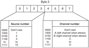
Figure 4.22: Format of byte 2 of consumer channel status.
Byte 4 of consumer channel status now contains an indication of the audio word length and the original sampling frequency of the signal. It used to be set to all zeros, so older equipment may show this characteristic. Bit 32 indicates whether the sample is maximum 20 or 24 bits (0 and 1 states respectively) and bits 3335 indicate the resolution in the same way as the professional interface (Table 4.4). The original sampling frequency indication in bits 3639 can be used to show the sampling frequency of a signal before sample rate conversion in a consumer playback system. This might be the case for applications such as computer games where sounds with low sampling frequencies could be internally converted to 44.1kHz for replay through a common convertor, or with DVD players where high sampling frequency material is down-converted to 44.1 or 48kHz for transmission over a standard digital interface. (Currently it is not permitted to transfer high sampling frequency material over an IEC 60958 digital interface in the DVD standard and digital outputs are limited to basic rates. This is an initial barrier to piracy of high resolution master material, although other procedures are being developed involving watermarking and encryption.)
4.8.6 Category Codes in Consumer Channel Status
The eight-bit category code identifies the source device, allowing subsequent channel status and user data to be interpreted correctly. Some examples of the most common category codes are shown in Table 4.9. (Note that category codes are normally written this way round, with the LSB first, which may be confusing since binary numbers are normally written down MSB first.)
| Category code (bits 815; LSB to MSB) | Device type |
|---|---|
| 00000000 | General |
| 10000000 | CD player |
| 1001001L | MiniDisc |
| 1001100L | DVD |
| 1100000L | DAT |
| 010XXXXL | DSP devices and digital/digital convertors |
As can be seen, all except the General and CD category codes have bit 15 as the 'L' bit. This is used in conjunction with the copyright bit to manage copy protection as explained in the next section. The CD standard was introduced before the copy protection issue became such a 'hot potato' and was stuck with the category code and copyright indication it first used. However, a workaround has been introduced whereby the copyright bit in byte 0 of channel status can be made to alternate states at a rate between 4 and 10 Hz to indicate a 'home copy' of original material of generation 1 or higher.
4.8.7 SCMS and Copy Protection
The method of coping with copy management is called SCMS (Serial Copy Management System) and is now implemented on all consumer digital recording equipment. SCMS applies when signals are copied digitally across a consumer format interface and has no meaning in the professional format. Although SCMS appears not to apply when a signal is copied via an analog interface, in fact there are problems as discussed below.
The principle of SCMS is that a copyright prerecorded signal may be copied only once (provided that the source device is one of the so-called 'white list' of product types from which limited copying is allowed), but no further generations are allowed. This is supposed to allow home users to make a single copy of something they have bought for their own purposes, but to prevent large scale piracy. The copyright protection (Cp) bit that already existed in the consumer format (bit 2) was not sufficient on its own because it did not give any indication of the generation of the copy. The so-called 'L bit' was therefore introduced in the category code (see previous section). The Cp bit in conjunction with the L bit can be used to prevent more than one generation of copying of copyright material. The state of the L bit in effect signifies the 'generation' of the signal, whether '0th generation' (an original prerecorded work) or 1st generation and higher copies. The Cp bit now signifies whether the source material is copyright or not ('0' = copyright). Unfortunately the complication does not stop here, because although the L bit is normally set so that in the '1' state it represents an original (commercially released, prerecorded software) rather than a copy, with laser optical products and broadcast receivers it is the other way around!
The upshot of all this is that if a recording device sees that the C bit of a digital source is '0' (copyright material) and the L bit indicates that the source is original prerecorded material, it will allow the copy. If the L bit indicates that the source is already a copy it will disallow the recording. When copyright material is copied from a prerecorded source a flag is recorded on the copy to state 'I am a copy of a copyright source', and when this recording is replayed the L bit will be set to show that it is not an original, thus disallowing further copies. Extremely thorough coverage of SCMS is to be found in an AES journal article by Sanchez 30 .
4.8.8 SCMS in DAT Machines
SCMS was first introduced because of the perceived threat of copying with DAT machines. It works in such machines as follows . There are two DAT category codes: one called simply 'DAT' (code 11000000) and one called 'DAT-P' (code 11000001) the difference between them is the L bit. On DAT recordings there are also two bits in the subcode recorded on the tape that controls copy protection and these are called the 'ID6' bits. An SCMS DAT machine looks at the ID6 bits recorded on the tape it is playing to determine how it should set the combination of L and C bits on the digital interface.
If the ID6 on the source tape is 00 (copies allowed) it will set the category to 'DAT' and the C bit to show 'non-copyright'. An SCMS machine receiving that signal would also set the recorded ID6 of the copy to 00, since there would be no reason to prevent further copies, and any number of serial digital copies might then be made.
If a DAT recorder sees a 'DAT-P' source it will allow copies no matter what the status of the C bit, whereas if it sees a straightforward 'DAT' source it will only allow a copy if the source is not copy protected. So if the ID6 on the source tape is 10 (copies not allowed), the source machine will set the category to 'DAT' and the C bit to 'copyright', then the recorder will not be able to copy that tape. If the ID6 on the source tape is 11 (one copy allowed), the machine will set the category to 'DAT-P' and the C bit to 'copyright', then a receiver would be able to record the signal (since DAT-P allows copies no matter what the status). It would know, though, that it was copying material. The ID6 of the copy would then automatically be set to 10 to prevent further copies.
Concerning copies made between DAT machines and other systems, or between pre-SCMS and SCMS machines, the following applies:
1 Digital Copies from CD
The CD category code (10000000) when recognized by an SCMS DAT machine will result in a copy whose ID6 is set to 10 (copies not allowed). (The L bit is '0' for original prerecorded material in laser optical products.)
2 Digital Copies from Other Digital Sources
Copies made from sources having the 'General' category code (00000000) will have their ID6 set to 11, whatever the status, allowing one further copy only. Sources asserting this code are likely to be such things as A/D convertors and some older DAT machines. It acknowledges that the source of the material is unclear, and might be copyright or might not.
3 Digital Copies to SCMS DAT Machines from Pre-SCMS Machines
Pre-SCMS machines may use either the 'General' category or the 'DAT' category, depending on when they were made and by whom. They will not normally be able to recognize the difference between a recorded ID6 of 11 and an ID6 of 10, because prior to SCMS the machine only had to look at one bit to detect status. Therefore such a machine will normally interpret both codes as indicating that the recording is copy protected (not even allowing one copy), and set the flag on the digital output.
Whether or not the receiver will record the data depends on whether the category is 'General' or 'DAT'. If it is 'General' then see 2 above. If it is 'DAT', then not even a single copy will be allowed. The only case in which unlimited copies will be allowed is when the source tape has an ID6 of 00, which is likely to be the case with many tapes recorded on pre-SCMS machines.
4 Digital Copies of Recordings Made from Analog Inputs
Unfortunately, SCMS DAT machines will set the ID6 of analog-sourced recordings to 11, thus allowing only one digital copy. This is a nuisance when the source is a perfectly legitimate non-copyright signal, such as one of your own private recordings.
5 Digital Copies of Prerecorded DAT Tapes
The ID6 of prerecorded tapes is set to 11, thus allowing one further copy if using an SCMS machine. If using a pre-SCMS replay machine, the 11 will be interpreted as 10 (see 3 above) and the bit will be asserted on the interface. A copy will only be possible if the category of the source machine is 'General', but not if it is 'DAT'.
6 Recording Non-Copy-Protected Material on SCMS Machines
There is no way to record completely unprotected material on an SCMS machine, except by feeding it with a digital source having a category code other than 'General' and a recorded ID6 of 00. This might be feasible if you have an early DAT machine. Even material recorded via the SCMS machine's analog inputs cannot be copied beyond a single generation.
7 Digital Copying from SCMS Machines to Pre-SCMS Machines
Such copies will only be possible at 48 kHz (or 32 kHz if you have such a tape); 44.1 kHz recordings will be blocked on unmodified machines. Source tapes with ID6 set to either 11 or 10 will cause the CP status to be asserted on the digital interface, and, since pre-SCMS machines tend to ignore the L bit, the copy will not be allowed at all. Source tapes with ID6 set to 00 may be copied.
8 Manual Setting of ID6 Status
Consumer machines will not allow the ID6 status of tapes to be set, but some recent professional machines will allow this.
4.8.9 Channel Status in Consumer CD Machines
It was originally intended that the first four bits of the Q subcode from the CD would be copied into the first four bits of the channel status data. The first four bits of Q subcode are as follows:
| Bit 0 | Two or four channel (two channel = '0') |
| Bit 1 | Undefined |
| Bit 2 | Copy protect |
| Bit 3 | Pre-emphasis |
Apart from bit 0 these are compatible with IEC 60958. Since CDs have never implemented a four-channel mode, bit 0 remains in the '0' state which is compatible with the 'consumer' status of bit 0 of IEC 60958. Other than this, the channel status format of the CD category code is the same as the general format, with the sampling frequency bits set to '0000' to indicate 44.1 kHz. The user bits contain the subcode information as discussed in section 4.7.2.
| | ||
| | ||
| | ||
EAN: 2147483647
Pages: 120