8.7 Protocol Testing
| | ||
| | ||
| | ||
8.7 Protocol Testing
In digital systems it is possible for problems to occur in which the data transmission is flawless but communication is still not achieved. This can happen where the transmitter and receiver have incompatible protocols. The protocol of a signal includes the nature and positioning of TRS patterns, the location of EDH blocks and embedded audio. A further consideration is that in order correctly to adjust analog-to-digital convertors it is necessary to monitor the actual code values coming from a convertor and compare them with the original analog voltages.
Such problems can only be addressed by use of a logic analyser. General-purpose logic analysers can be used on parallel interfaces, but for best results a dedicated digital video analyser is to be preferred. Figure 8.10 shows the layout of a video analyser. An SDI receiver and/or a parallel receiver drive a decoder that identifies TRS patterns for synchronizing purposes. Incoming words are written into a page of RAM that can hold the contents of a few lines of video. The analyser thus takes a snapshot of interface activity. The point within the frame at which the snapshot is taken is determined by the trigger criteria provided to the RAM write logic.
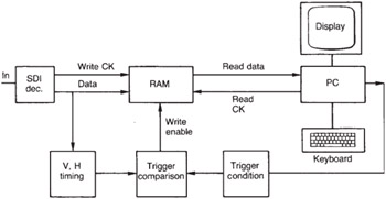
Figure 8.10: A video analyser allows a snapshot of digital video interface activity to be captured in RAM. This data can then be inspected at leisure using a small computer.
Once the RAM is written in real time with the digital video snapshot, the data are frozen and can be inspected using the associated PC and its display. Signals can be displayed graphically as they would appear on conventional analog waveform monitors or vectorscopes, but can also be displayed as tabular data so that the exact binary word values and positions can be established. Any departures from correct protocol can be detected by comparing the data with the relevant standards.
Figure 8.11 shows how a video analyser is used to set up a component ADC. Convertor set-up is critical as digital systems keep the data the same all down the line, so it has to be right from the outset. A precise analog test pattern generator is used to produce colour bars. The signal is looped through an analog waveform monitor to the ADC where it should be terminated with the actual terminator to be used in practice. This is necessary because terminator tolerance is such that changing a terminator can change the analog level by several digital code values. The generator level is adjusted until the waveform monitor displays exactly the correct amplitude in, say, the white bar.
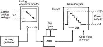
Figure 8.11: Using a video analyser to set the gain of an ADC. The ADC output data are compared with standard values on a known part of the analog waveform.
The analyser then captures the ADC output and the black bar is located in waveform mode with the cursor. The actual data values at the cursor position are displayed, and these can be compared with the ideal so that any offset in the convertor can be revealed and adjusted out. By selecting the white bar the luminance convertor gain can be adjusted. Some analysers allow timed retriggering so that a new snapshot is taken periodically. This mode is useful when making dynamic gain adjustments. The colour difference signal gains are set up in a similar manner.
The analog Y/C timing should be checked with a suitable signal such as bowtie before returning to colour bars to check the relative timings of the green/ magenta transitions in the three digital components . This is not as easy as it sounds as the colour difference sample spacing is twice that of luminance and the sample values need to be interpreted carefully to find the transition.
| | ||
| | ||
| | ||
EAN: 2147483647
Pages: 120