8.6 Margining
| | ||
| | ||
| | ||
8.6 Margining
It is a characteristic of digital systems that failure is sudden because deteriorations in the signal are initially rejected until they grow serious enough to corrupt data. Put simply, just because a digital system is working today, there is no guarantee that it will work tomorrow unless its performance margin can be measured. Margining is a long established technique used in the computer industry to prove the reliability of a digital process by testing it under conditions more stressful than will be encountered in service. The degree of additional stress that can be applied before failure is a measure of the performance margin. As digital video is only data, margining techniques can be applied to it with great success and if used correctly will give a much needed confidence factor.
There are two ways in which an SDI system can be stressed. The first of these is to use a special signal generator producing pathological test patterns. These are bitstreams that mimic the convolution process of the SDI scrambler and result in channel signals containing less clock content and lower frequencies than usual. Receivers find it harder to decode pathological signals and so they will result in errors unless the system is in good shape.
A simple alternative to the pathological test signal is the use of a cable simulator that has the same effect as increasing the length of the cable between transmitter and receiver. The Faraday ˜cable clone' is the best known of these devices. Figure 8.4 shows the non-linear relationship between cable length and error rate and illustrates the ˜crash knee' in the characteristic. Testing with a cable simulator depends upon the existence of the crash knee. Figure 8.9(a) shows how the test is made. The cable under test is temporarily broken and the ˜cable clone' is inserted. An error-monitoring system such as EDH or a signature analyser is connected after the receiver under test.
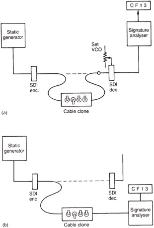
Figure 8.9: Margin testing requires the cable under test to be broken and a ˜cable clone' or simulator to be inserted as in (a). The cable length is artificially increased until the crash knee is reached. The configuration in (b) is incorrect as the receiver to be used in service is not being tested. In fact the signature analyser's receiver is being tested a meaningless exercise.
The configuration shown in (b) is incorrect as it only tests the cable and the transmitter in conjunction with the receiver in the signature analyser. The important receiver is not tested. The cable clone must be installed in the cable and the signature analyser must be connected after the receiver under test.
With the cable clone set to bypass, the system should show no errors. If errors are detected the fault should be rectified. Starting with an error-free system the cable length is gradually increased until a rapid increase in error rate indicates that the crash knee has been reached. The additional length of cable needed to reach the crash knee is a direct measure of the performance margin or head height. It will be seen from Figure 8.4 that the error rate changes from negligible to intolerable with an increase in length of only 2030 metres. Clearly if less than this figure is achieved in the margining test the system is marginal and should not be put into service.
One potential problem area frequently overlooked is to ensure that the VCO in the receiving phase-locked loop is correctly centred. If it is not, it will be running with a static phase error and will not sample the received waveform at the centre of the eyes. The sampled bits will be more prone to noise and jitter errors. VCO centring can be checked in a number of ways. If a frequency meter is available, this can be used to display the VCO frequency without input. Another method is to display the control voltage. This should not change significantly when the input is momentarily disconnected. However, the best method is to adjust for minimum error rate in conjunction with margining. Errors can be seen on a video monitor.
Using a cable clone, cable length is added until a slight error rate is caused. The VCO centre frequency is now adjusted one way or the other to see if the error rate can be reduced or even eliminated. If there is a range of error-free adjustment, more cable length should be switched in to make a finer adjustment.
In many receivers, the phase-locked loop will stay in lock more readily than it can achieve lock. Thus the VCO can be misadjusted whilst a signal is being received and will continue to lock to it. However, if the input signal is interrupted , lock will be lost. Consequently a good method is to adjust for the minimum errors after an interruption of the signal.
Some early SDI receivers run quite hot and the VCO centre frequency changes with temperature. Placing cards on an extender board may change the airflow enough to alter the centre frequency.
| | ||
| | ||
| | ||
EAN: 2147483647
Pages: 120