Understanding Drawing Principles
 | |||||||||||
| Chapter 19 - Graphics with GDI+ | |
| bySimon Robinsonet al. | |
| Wrox Press 2002 | |
In this section, we'll examine the basic principles that we need to understand in order to start drawing to the screen. We'll start by giving an overview of GDI, the underlying technology on which GDI+ is based, and see how it and GDI+ are related . Then we'll move on to a couple of simple examples.
GDI and GDI+
In general, one of the strengths of Windows - and indeed of modern operating systems in general - lies in their ability to abstract the details of particular devices away from the developer. For example, you don't need to understand anything about your hard drive device driver in order to programmatically read and write files to disk; you simply call the appropriate methods in the relevant .NET classes (or in pre-.NET days, the equivalent Windows API functions). This principle is also very true when it comes to drawing. When the computer draws anything to the screen, it does so by sending instructions to the video card. However, there are many hundreds of different video cards on the market, most of which have different instruction sets and capabilities. If you had to take that into account, and write specific code for each video driver, writing any such application would be an almost impossible task. This is why the Windows Graphical Device Interface ( GDI ) has always been around since the earliest versions of Windows.
GDI provides a layer of abstraction, hiding the differences between the different video cards. You simply call the Windows API function to do the specific task, and internally the GDI figures out how to get your particular video card to do whatever it is you want. Not only this, but if you have several display devices - monitors and printers, say - GDI achieves the remarkable feat of making your printer look the same as your screen as far as your application is concerned . If you want to print something instead of displaying it, you simply inform the system that the output device is the printer and then call the same API functions in exactly the same way.
As you can see, the DC is a very powerful object and you won't be surprised to learn that under GDI all drawing had to be done through a device context. The DC was even used for operations that don't involve drawing to the screen or to any hardware device, such as modifying images in memory.
Although GDI exposes a relatively high-level API to developers, it is still an API that is based on the old Windows API, with C-style functions. GDI+ to a large extent sits as a layer between GDI and your application, providing a more intuitive, inheritance-based object model. Although GDI+ is basically a wrapper around GDI, Microsoft has been able through GDI+ to provide new features and claims to have made some performance improvements.
The GDI+ part of the .NET base class library is huge, and we will scarcely scratch the surface of its features in this chapter. That's a deliberate decision, because trying to cover more than a tiny fraction of the library would have effectively turned this chapter into a huge reference guide that simply listed classes and methods. It's more important to understand the fundamental principles involved in drawing, so that you will be in a good position to explore the classes available yourself. Full lists of all the classes and methods available in GDI+ are of course available in the MSDN documentation.
Developers coming from a VB background, in particular, are likely to find the concepts involved in drawing quite unfamiliar, since VB's focus lies so strongly in controls that handle their own painting. Those coming from a C++/MFC background are likely to be in more comfortable territory since MFC does require developers to take control of more of the drawing process, using GDI. However, even if you have a good background in GDI, you'll find a lot of the material is new.
GDI+ Namespaces
Here's an overview of the main namespaces you'll need to look in to find the GDI+ base classes:
| Namespace | Contains |
|---|---|
| System.Drawing | Most of the classes, structs, enums, and delegates concerned with the basic functionality of drawing |
| System.Drawing.Drawing2D | Provides most of the support for advanced 2D and vector drawing, including antialiasing, geometric transformations, and graphics paths |
| System.Drawing.Imaging | Various classes that assist in the manipulation of images (bitmaps, GIF files, and so on) |
| System.Drawing.Printing | Classes to assist when specifically targeting a printer or print preview window as the "output device" |
| System.Drawing.Design | Some predefined dialog boxes, property sheets, and other user interface elements concerned with extending the design-time user interface |
| System.Drawing.Text | Classes to perform more advanced manipulation of fonts and font families |
You should note that almost all of the classes and structs that we use in this chapter will be taken from the System.Drawing namespace.
Device Contexts and the Graphics Object
In GDI, the way that you identify which device you want your output to go to is through an object known as the device context (DC). The DC stores information about a particular device and is able to translate calls to the GDI API functions into whatever instructions need to be sent to that device. You can also query the device context to find out what the capabilities of the corresponding device are (for example, whether a printer prints in color or only black and white), so you can adjust your output accordingly . If you ask the device to do something it's not capable of, the DC will normally detect this, and take appropriate action (which depending on the situation might mean throwing an error or modifying the request to get the closest match that the device is actually capable of).
However, the DC doesn't only deal with the hardware device. It acts as a bridge to Windows and is able to take account of any requirements or restrictions placed on the drawing by Windows. For example, if Windows knows that only a portion of your application's window needs to be redrawn, the DC can trap and nullify attempts to draw outside that area. Due to the DC's relationship with Windows, working through the device context can simplify your code in other ways.
For example, hardware devices need to be told where to draw objects, and they usually want coordinates relative to the top left corner of the screen (or output device). Usually, however, your application will be thinking of drawing something at a certain position within the client area (the area reserved for drawing) of its own window, possibly using its own coordinate system. Since the window might be positioned anywhere on the screen, and a user might move it at any time, translating between the two coordinate systems is potentially a difficult task. However, the DC always knows where your window is and is able to perform this translation automatically.
With GDI+, the device context is wrapped up in the .NET base class System.Drawing.Graphics . Most drawing is done by calling methods on an instance of Graphics . In fact, since the Graphics class is the class that is responsible for actually handling most drawing operations, very little gets done in GDI+ that doesn't involve a Graphics instance somewhere, so understanding how to manipulate this object is the key to understanding how to draw to display devices with GDI+.
Drawing Shapes
We're going to start off with a short example, DisplayAtStartup , to illustrate drawing to an application's main window. The examples in this chapter are all created in Visual Studio.NET as C# Windows applications. Recall that for this type of project the code wizard gives us a class called Form1 , derived from System.Windows.Form , which represents the application's main window. Unless otherwise stated, in all code samples, new or modified code means code that we've added to the wizard-generated code.
In .NET usage, when we are talking about applications that display various controls, the terminology form has largely replaced window to represent the rectangular object that occupies an area of the screen on behalf of an application. In this chapter, we've tended to stick to the term window, since in the context of manually drawing items it's rather more meaningful. We'll also talk about the Form when we're referring to the .NET class used to instantiate the form/window. Finally, we'll use the terms drawing and painting interchangeably to describe the process of displaying some item on the screen or other display device.
The first example will simply create a form and draw to it in the constructor, when the form starts u p . I should say at the start that this is not actually the best or the correct way to draw to the screen - we'll quickly find that this example has a problem in that it is unable to redraw anything when it needs to after starting up. However the sample will illustrate quite a few points about drawing without our having to do very much work.
For this sample, we start Visual Studio .NET and create a Windows application. We first set the background color of the form to white. We've put this line in the InitializeComponent() method so that Visual Studio .NET recognizes the line and is able to alter the design view appearance of the form. We could have used the design view to set the background color, but this would have resulted in pretty much the same line being added automatically:
private void InitializeComponent() { this.components = new System.ComponentModel.Container(); this.Size = new System.Drawing.Size(300,300); this.Text = "Display At Startup"; this.BackColor = Color.White; Then we add code to the Form1 constructor. We create a Graphics object using the Form's CreateGraphics() method. This Graphics object contains the Windows DC we need to draw with. The device context created is associated with the display device, and also with this window:
public Form1() { InitializeComponent(); Graphics dc = this.CreateGraphics(); this.Show(); Pen bluePen = new Pen(Color.Blue, 3); dc.DrawRectangle(bluePen, 0,0,50,50); Pen redPen = new Pen(Color.Red, 2); dc.DrawEllipse(redPen, 0, 50, 80, 60); } As you can see, we then call the Show() method to display the window. This is really a fudge to force the window to display immediately, because we can't actually do any drawing until the window has been displayed - there's nothing to draw onto.
Finally, we display a rectangle, at coordinates (0,0), and with width and height 50, and an ellipse with coordinates (0,50) and with width 80 and height 50. Note that coordinates (x,y) means x pixels to the right and y pixels down from the top left corner of the client area of the window - and these are the coordinates of the top left corner of the shape being displayed:
The overloads that we are using of the DrawRectangle() and DrawEllipse() methods each take five parameters. The first parameter of each is an instance of the class System.Drawing.Pen . A Pen is one of a number of supporting objects to help with drawing - it contains information about how lines are to be drawn. Our first pen says that lines should be blue and with a width of 3 pixels, the second says that lines should be red and have a width of 2 pixels. The final four parameters are coordinates and size. For the rectangle, they represent the (x,y) coordinates of the top left hand corner of the rectangle, and its width and height. For the ellipse these numbers represent the same thing, except that we are talking about a hypothetical rectangle that the ellipse just fits into, rather than the ellipse itself.
Running this code gives this result:
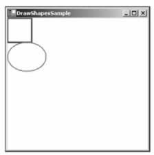
I know - the book's printed in grayscale. As with all the screenshots in this chapter, you'll just have to take my word for it that the colors are correct. Or you can always try running the examples yourself!
This screenshot demonstrates a couple of points. First, you can see clearly what the client area of the window means. It's the white area - the area that has been affected by our setting the BackColor property. And notice that the rectangle nestles up in the corner of this area, as you'd expect when we specified coordinates of (0,0) for it. Second, notice how the top of the ellipse overlaps the rectangle slightly, which you wouldn't expect from the coordinates we gave in the code. That results from where Windows places the lines that border the rectangle and ellipse. By default, Windows will try to center the line on where the border of the shape is - that's not always possible to do exactly, because the line has to be drawn on pixels (obviously), but normally the border of each shape theoretically lies between two pixels. The result is that lines that are 1 pixel thick will get drawn just inside the top and left sides of a shape, but just outside the bottom and right sides - which means that shapes that strictly speaking are next to each other will have their borders overlap by one pixel. We've specified wider lines; therefore the overlap is greater. It is possible to change the default behavior by setting the Pen.Alignment property, as detailed in the MSDN documentation, but for our purposes the default behavior is adequate.
Unfortunately, if you actually run the sample you'll notice the form behaves a bit strangely. It's fine if you just leave it there, and it's fine if you drag it around the screen with the mouse. Try minimizing it then restoring it, however, and our carefully drawn shapes just vanish ! The same thing happens if you drag another window across the sample. If you drag another window across it so that it only obscures a portion of our shapes, then drag the other window away again, you'll find the temporarily obscured portion has disappeared and you're left with half an ellipse or half a rectangle!
So what's going on? The problem arises when part of a window gets hidden, because Windows usually immediately discards all the information concerning exactly what was being displayed there. It has to - otherwise the memory usage for storing screen data would be astronomical. A typical computer might be running with the video card set to display 1024 x 768 pixels, perhaps with 24-bit color mode. We'll cover what 24-bit color means later in the chapter, but for now I'll say that implies that each pixel on the screen occupies 3 bytes. That means 2.25MB to display the screen. However, it's not uncommon for a user to sit there working, with 10 or 20 minimized windows in the taskbar. Let's do a worst-case scenario: 20 windows, each of which would occupy the whole screen if it wasn't minimized. If Windows actually stored the visual information those windows contained, ready for when the user restored them, you'd be talking about 45MB! These days, a good graphics card might have 64MB of memory and be able to cope with that, but it's only a couple of years ago that 4MB was considered generous in a graphics card - and the excess would need to be stored in the computer's main memory. A lot of people still have old machines - for example, my backup computer that has a 4 MB graphics card. Clearly it wouldn't be practical for Windows to manage its user interface like that.
The moment any part of a window gets hidden, the 'hidden' pixels get lost, because Windows frees the memory that was holding those pixels. It does, however, note that a portion of the window is hidden, and when it detects that it is no longer hidden, it asks the application that owns the window to redraw its contents. There are a couple of exceptions to this rule - generally for cases in which a small portion of a window is hidden very temporarily (a good example is when you select an item from the main menu and that menu item drops down, temporarily obscuring part of the window below). In general, however, you can expect that if part of your window gets hidden, your application will need to redraw it later.
That's the source of the problem for our sample application. We placed our drawing code in the Form1 constructor , which is called just once when the application starts up, and you can't call the constructor again to redraw the shapes when required later on.
In next section, we will modify our sample to do just that.
Painting Shapes Using OnPaint()
If the above explanation has made you worried that drawing your own user interface is going to be terribly complicated, don't worry. Getting your application to redraw itself when necessary is actually quite easy.
Windows notifies an application that some repainting needs to be done by raising a Paint event. Interestingly, the Form class has already implemented a handler for this event so you don't need to add one yourself. The Form1 handler for the Paint event will at some point in its processing call up a virtual method, OnPaint() , passing to it a single PaintEventArgs parameter. This means that all we need to do is override OnPaint() to perform our painting.
Although we've chosen to work by overriding OnPaint() , it's equally possible to achieve the same results by simply adding our own event handler for the Paint event (a Form1_Paint() method, say) - in much the same way as you would for any other Windows Forms event. This other approach is arguably more convenient , since you can add a new event handler through the VS .NET properties window, saving yourself from typing some code. However, our approach, of overriding OnPaint() , is slightly more flexible in terms of letting us control when the call to the base class window processing occurs, and is the approach recommended in the documentation. We suggest you use this approach for consistency.
We'll create a new Windows Application called DrawShapes to do this. As before, we set the background color to white using the Properties Window. We'll also change the Form's text to 'DrawShapes sample'. The n we add the following code to the generated code for the Form1 class:
protected override void OnPaint( PaintEventArgs e ) { base.OnPaint(e); Graphics dc = e.Graphics; Pen bluePen = new Pen(Color.Blue, 3); dc.DrawRectangle(bluePen, 0,0,50,50); Pen redPen = new Pen(Color.Red, 2); dc.DrawEllipse(redPen, 0, 50, 80, 60); }
Notice that OnPaint() is declared as protected , because it is normally used internally within the class, so there's no reason for any other code outside the class to know about its existence.
PaintEventArgs is a class that is derived from the EventArgs class normally used to pass in information about events. PaintEventArgs has two additional properties, of which the more important is a Graphics instance, already primed and optimized to paint the required portion of the window. This means that you don't have to call CreateGraphics() to get a DC in the OnPaint() method - you've already been provided with one. We'll look at the other additional property soon - it contains more detailed information about which area of the window actually needs repainting.
In our implementation of OnPaint() , we first get a reference to the Graphics object from PaintEventArgs , then we draw our shapes exactly as we did before. At the end we call the base class's OnPaint() method. This step is important. We've overridden OnPaint() to do our own painting, but it's possible that Windows may have some additional work of its own to do in the painting process - any such work will be dealt with in an OnPaint() method in one of the .NET base classes.
For this example, you'll find that removing the call to base.OnPaint() doesn't seem to have any effect, but don't ever be tempted to leave this call out. You might be stopping Windows from doing its work properly and the results could be unpredictable.
OnPaint() will also be called when the application first starts up and our window is displayed for the first time, so there is no need to duplicate the drawing code in the constructor.
Running this code gives the same results initially as for our previous example - except that now our application behaves itself properly when you minimize it or hide parts of the window.
Using the Clipping Region
Our DrawShapes sample from the last section illustrates the main principles involved with drawing to a window, although it's not very efficient. The reason is that it attempts to draw everything in the window, irrespective of how much needs to be drawn. Consider the situation shown in this screenshot. I ran the DrawShapes example, but while it was on the screen I opened another window and moved it over the DrawShapes form, so it hid part of it.
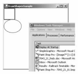
So far, so good. However, when I move the overlapping window so that the DrawShapes window is fully visible again, Windows will as usual send a Paint event to the form, asking it to repaint itself. The rectangle and ellipse both lie in the top left corner of the client area, and so were visible all the time; therefore, there's actually nothing that needs to be done in this case apart from repaint the white background area. However, Windows doesn't know that, so it thinks it should raise the Paint event, resulting in our OnPaint() implementation being called. OnPaint() will then unnecessarily attempt to redraw the rectangle and ellipse.
Actually, in this case, the shapes will not get repainted. The reason is to do with the device context. Windows has pre- initialized the device context with information concerning what area actually needed repainting. In the days of GDI, the region that is marked for repainting used to be known as the invalidated region , but with GDI+ the terminology has largely changed to clipping region . The device context knows what this region is; therefore, it will intercept any attempts to draw outside this region, and not pass the relevant drawing commands on to the graphics card. That sounds good, but there's still a potential performance hit here. We don't know how much processing the device context had to do before it figured out that the drawing was outside the invalidated region. In some cases it might be quite a lot, since calculating which pixels need to be changed to what color can be very processor- intensive (although a good graphics card will provide hardware acceleration to help with some of this).
The bottom line to this is that asking the Graphics instance to do some drawing outside the invalidated region is almost certainly wasting processor time and slowing your application down. In a well designed application, your code will actively help the device context out by carrying out a few simple checks, to see if the proposed drawing work is likely to be actually needed, before it calls the relevant Graphics instance methods. In this section we're going to code up a new example - DrawShapesWithClipping - by modifying the DisplayShapes example to do just that. In our OnPaint() code, we'll do a simple test to see whether the invalidated region intersects the area we need to draw in, and only call the drawing methods if it does.
First, we need to obtain the details of the clipping region. This is where an extra property, ClipRectangle , on the PaintEventArgs comes in. ClipRectangle contains the coordinates of the region to be repainted, wrapped up in an instance of a struct, System.Drawing.Rectangle . Rectangle is quite a simple struct - it contains four properties of interest: Top , Bottom , Left, and Right . These respectively contain the vertical coordinates of the top and bottom of the rectangle, and the horizontal coordinates of the left and right edges.
Next, we need to decide what test we'll use to determine whether drawing should take place. We'll go for a simple test here. Notice, that in our drawing, the rectangle and ellipse are both entirely contained within the rectangle that stretches from point (0,0) to point (80,130) of the client area; actually, point (82,132) to be on the safe side, since we know that the lines may stray a pixel or so outside this area. So we'll check whether the top left corner of the clipping region is inside this rectangle. If it is, we'll go ahead and redraw. If it isn't, we won't bother.
Here is the code to do this:
protected override void OnPaint( PaintEventArgs e ) { base.OnPaint(e); Graphics dc = e.Graphics; if (e.ClipRectangle.Top < 132 && e.ClipRectangle.Left < 82) { Pen bluePen = new Pen(Color.Blue, 3); dc.DrawRectangle(bluePen, 0,0,50,50); Pen redPen = new Pen(Color.Red, 2); dc.DrawEllipse(redPen, 0, 50, 80, 60); } } Note that what gets displayed is exactly the same as before - but performance is improved now by the early detection of some cases in which nothing needs to be drawn. Notice, also that we've chosen a fairly crude test of whether to proceed with the drawing. A more refined test might be to check separately, whether the rectangle needs to be drawn, or whether the ellipse needs to be redrawn, or both. However, there's a balance here. You can make your tests in OnPaint() more sophisticated, improving performance, but you'll also make your own OnPaint() code more complex. It's almost always worth putting some test in, because you've written the code so you understand far more about what is being drawn than the Graphics instance, which just blindly follows drawing commands.
EAN: 2147483647
Pages: 244