About Aligning and Snapping Objects
|
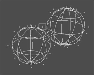
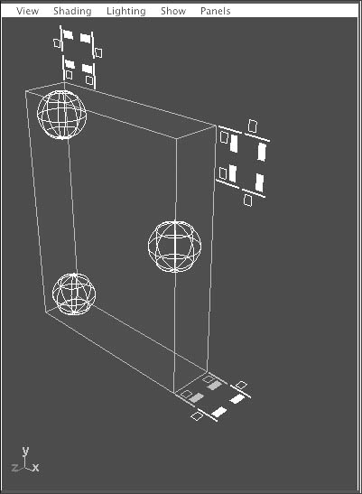
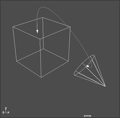
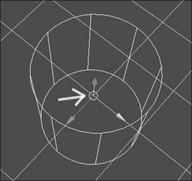
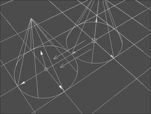
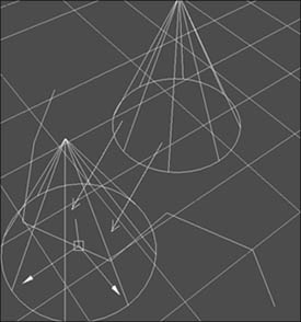
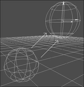
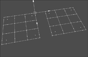
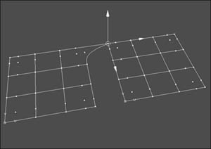
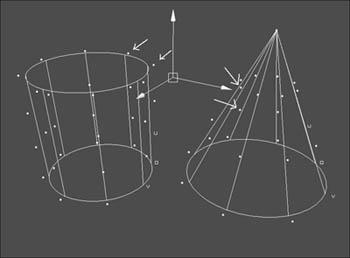
| In the real world, objects touch each other to form other objects. A room, for example, is formed by multiple adjoining walls. You can use Maya's alignment tools to line up objects and components (Figure 6.20), saving the additional steps it would take to align objects by eye and eliminating the uncertainty over whether the objects actually touch each other. Figure 6.20. You can align one point on one surface to one point on another surface. Here one point on each surface has been selected and the point-to-point command has been run, so that now the two select points are on top of each other (inside the square). Maya's alignment options include the Snap Align and Snap Together tools. The Snap Align tool is especially easy to control because it's completely icon-based (Figure 6.21)which means there's no Options window to fuss with. This is a great tool for aligning one object to another, giving you multiple alignment choices (for example, aligning one object to another's center, top, or bottom just by clicking the respective icon). The Snap Together tool takes alignment even further by allowing you to move and rotate an object while aligning it (Figure 6.22). Figure 6.21. Graphical elements are used as quick alignment tools. Figure 6.22. Arrows appear when the alignment tool is invoked to show how the alignment command will affect the surfaces when |
1. | Select an object. |
2. | Select the Move tool. |
3. | Hold down Figure 6.28. The center point of the surface is used to snap from gridline to gridline. or Click The pivot point of the object snaps to the grid corner where you clicked with the middle mouse button. |
4. | Release the mouse to finalize the snapping position. |
To snap an object to a curve:
1. | Select an object. |
2. | Select the Move tool. |
3. | Hold down Figure 6.29. The surface's center point will slide across the curve until you release the mouse button. or Click The pivot point of the object jumps to the curve where you clicked with the middle mouse button. |
4. | Release the mouse to finalize the snapping position. |
To snap an object to a view plane:
1. | Select an object. |
2. | Select the Move tool. |
3. | Click Figure 6.30. The pivot point of the object snaps to the view plane where you clicked with your middle mouse button. |
To snap a point on one surface to a point on another surface:
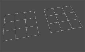
1. | Create two NURBS planes (Figure 6.31). Figure 6.31. Separate two primitive planes so that you can easily view the snapping results. |
2. | Select both planes and press |
3. | Select a corner CV on one of the planes (Figure 6.32). Figure 6.32. Select the point you would like to snap into alignment with another point. |
4. | Select the Move tool. |
5. | Hold down Figure 6.33. Any selected point can be snapped to any edit point or CV. |
 Tips
Tips
Although you can use the left mouse button when snapping, using the middle mouse button prevents unwanted objects from accidentally being selected.
Although we showed snapping points on a curve in this example, the same technique can be used to snap a point on one object to a point on another object. You can snap any point to any other point on a surface or a curve, on the same object or a different object.
The Snap Align tools
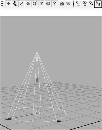
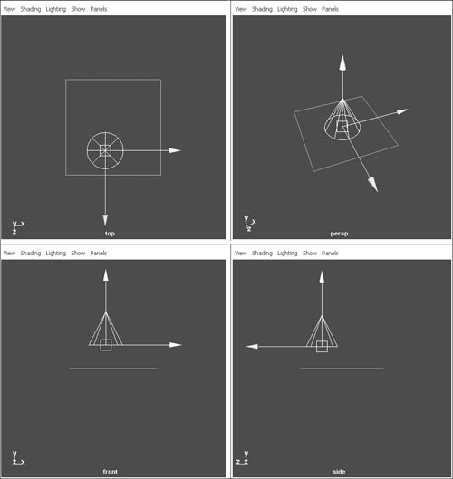
The Snap Align tools are a set of alignment aids for placing multiple objects. Alignment is very important in the world of 3D modeling because an object can appear to be aligned in the Perspective view but be completely off in the orthographic views (Figure 6.34). This happens because the camera angles of orthographic views are straight on from the side, top, and right; whereas the Perspective view can be viewed at any angle, often giving you an inaccurate perception of the scene.
Figure 6.34. The cone seems to be centered on the plane in the Perspective view, but in the orthographic views, you can see that it's actually very much out of alignment.
The Snap Alignment tools include the Point-to-Point Snaps, Snap Align Objects, Snap Align Tool, and the Snap Together Toolall of which are essential to a streamlined workflow. Many of the alignment tools are similar; you'll soon determine which one best fits your workflow.
To align two or more objects using the Align Objects tool:
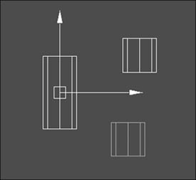
1. | Create two primitive cylinders (making one taller along the Y axis) with some space between them (Figure 6.35). Figure 6.35. The cylinders are different sizes to better illustrate the change after alignment. |
2. | Select the cylinders. |
3. | From the Modify menu select the box beside Snap Align Objects > Align Objects. |
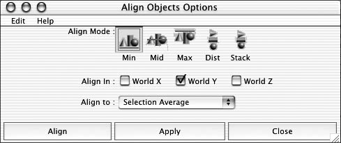
4. | Select Min Figure 6.36. Min |
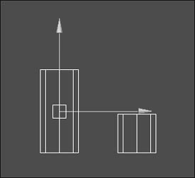
5. | Click Apply. Figure 6.37. The bases of the two surfaces are now placed on the same grid line. |
6. | With the Align Objects Options dialog box still open, select Mid |
7. | Click Align. Figure 6.38. The two surfaces are aligned to their centers. |
To evenly distribute multiple objects along an axis using the Align Objects tool:
1. | Create a primitive cylinder. |
2. | Duplicate the cylinder four times. |
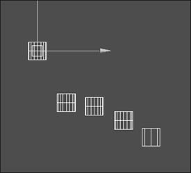
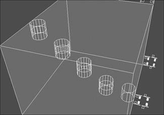
3. | Move one of the cylinders up the Y axis 10 grid units (Figure 6.39). Figure 6.39. Only the placement of the two surfaces farthest away from each other matters now because the rest of the objects will be distributed evenly between them. |
4. | Select all of the cylinders. |
5. | From the Modify menu select the box beside Snap Align Objects > Align Objects. |
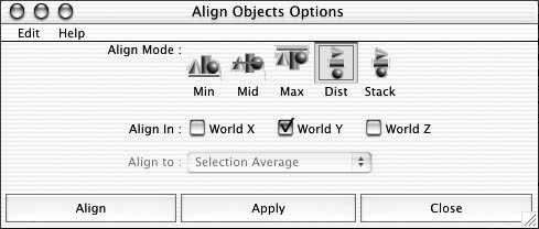
6. | Select Dist Figure 6.40. The Dist option can be used to evenly distribute the selected objects along the selected axes. Setting the World to Y forces the objects to be distributed along the Y axis. |
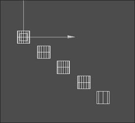
7. | Click Apply. Figure 6.41. The cylinders are perfectly spaced along the Y axis. |
To align two or more objects using the Align tool:
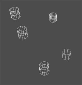
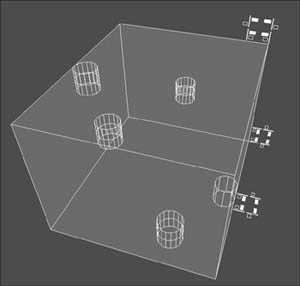
1. | Create five primitive cylinders and randomly space them away from each other (Figure 6.42). Figure 6.42. The order of selection becomes important because the objects are aligned to the last selected object. |
2. | Select one cylinder by clicking it, then |
3. | From the Modify menu, select the box beside Snap Align Objects > Align Tool. Figure 6.43. A gray bounding box is for visualization purposes only: You need to click the icons for the Align function to work. |
4. | Click Figure 6.44. Note that each icon actually illustrates the side, or center, on which the alignment will occur. The cylinders fall into alignment with the selected icon. |
5. | Press |
6. | Repeat the last step until you feel comfortable with each of the alignment icons functions. |
 Tip
Tip
Objects are aligned to the last selected object (blue).
To use the Point-to-Point Snap Align tool:
1. | Create one primitive cylinder and one primitive cone. |
2. | Select the objects and press |
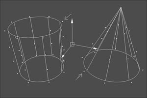
3. | Select one CV from the cylinder, then Figure 6.45. You can select any edit point or CV to be aligned with any edit point or CV on another surface. |
4. | From the Modify menu, select the box beside Snap Align Objects > Point to Point. Figure 6.46. The two selected points now appear as one but are actually sitting on top of each other. |
 Tip
Tip
If you only want the points to move into alignment, not the entire object, use Point Snap (explained earlier in this chapter) instead of the Point-to-Point Snap Align Tool.
To use the 2 and 3 Point-to-Point Snap Align tools:
1. | Create one primitive cylinder and one primitive cone. |
2. | Select the objects and press |
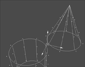
3. | Select two CVs from the cylinder, then Figure 6.47. The selected set of points will be aligned to the other selected points as closely as possible without changing the shape of the surface. or Select three CVs from the cylinder, then |
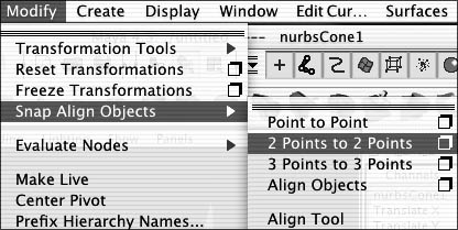
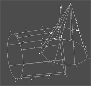
4. | If you selected two CVs on each object, from the Modify menu, select the box beside Snap Align Objects > 2 Points to 2 Points. If you selected three points on each object, select the box beside Snap Align Objects > 3 Points to 3 Points (Figure 6.48). Figure 6.48. The Snap Align Objects drop-down menu holds many of the alignment commands. The entire object with the first selected points moves into alignment with the second object's selected points. The points may not stack on top of one another if the spacing between points is different on each of the objects (Figure 6.49). Figure 6.49. The cylinder's placement shifts into alignment with the selected points on the cone's surface. |
|
