CCK
|
| < Day Day Up > |
|
CCK allows for multi-channel operation in the 2.4 GHz band by virtue of using the existing 802.11 1 and 2 Mbps DSSS channelization scheme. The spreading employs the same chipping rate and spectrum shape as the 802.11 Barker Sequence, allowing for three non-interfering channels in the 2.4 to 2.483 GHz band. Thus CCK modulation provides for a spectrum similar to that of the original 802.11 systems, at least at the low bandwidths. This allows interoperability with the original 802.11's DSSS modulation technique and it also allows for 802.11b multi-channel operation in the 2.4 GHz band using the existing 802.11 DSSS channel structure scheme.
CCK modulation consists of a set of 64 eight-bit code words. As a set, these code words have unique mathematical properties that allow them to be accurately distinguished from one another by a receiver even in the presence of substantial noise and multipath interference (e.g., interference caused by receiving multiple radio reflections within a building). The 5.5 Mbps rate uses CCK to encode 4 bits per symbol, while the 11 Mbps rate encodes 8 bits per symbol. Actually, to attain 11 Mbps CCK modulation, 6 bits of the 8 are used to select one of 64 symbols of 8 chip length for the symbol and the other 2 bits are used by QPSK to modulate the entire symbol. This results in modulating 8 bits onto each symbol. The chipping rate is maintained at 11 million chip bits per second for all modes. Both speeds use QPSK as the modulation technique and signal at 1.375 million symbols per second.
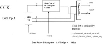
Figure 5.4: This graphic shows how the CCK modulation is formed. Graphic courtesy of Intersil.
The FCC regulations for the ISM band require at least 10 decibel (dB) of processing gain (11 dB for 802.11), which is normally achieved with spread spectrum techniques. CCK can achieve this gain too without having to be a conventional spread spectrum signal. Rather than using one or two 11-bit Barker sequences, CCK uses a series of codes called "complementary sequences." Because there are 64 unique code word sets that can be used to encode the signal, up to 6 bits can be represented by any one particular code word (instead of the single bit represented by a Barker symbol).
The wireless radio transmitter device generates a 2.4 GHz carrier wave (2.4 to 2.483 GHz) and modulates that wave using a various techniques, depending on the circumstances. For a 1 Mbps transmission, BPSK is used (one phase shift for each bit). To accomplish 2 Mbps or greater transmission, more sophisticated QPSK is used. QPSK can encode two bits of information in the same space as BPSK encodes one. The tradeoff is the need for increased power or else one must decrease the range to maintain signal quality.
Unfortunately, the FCC regulates the output power of portable radios to just one Watt; therefore, as the 802.11 transceiver moves away from the radio, the radio must adapt to the situation by using a less complex (and slower) encoding mechanism to send data. Ironically, the CCK code word is modulated with the same QPSK technology that was used in 2 Mbps wireless direct spread radios. This enables an additional 2 bits of information to be encoded in each symbol. Eight binary "chip" numbers are sent for each 6 bits, but each symbol encodes 8 bits thanks to the QPSK modulation. So, for a 1 Mbps transmission, 11 million chip bits per second times 2 MHz equals 22 MHz of spectrum. Likewise, for a 2 Mbps transmission, 2 bits per symbol are modulated with QPSK, 11 million chips per second, and thus you need 22 MHz of spectrum. In short, to transmit at a bit rate of 11 Mbps, you need 22 MHz of frequency spectrum.
|
| < Day Day Up > |
|
EAN: 2147483647
Pages: 273