POS Interfaces
|
|
With the correct loopback addressing in r3 and r4, we can now move on to common configuration requirements and testing techniques for Packet Over SONET (POS) interfaces. Figure 2.1 details the specifics of the POS interfaces connecting r3 and r4.
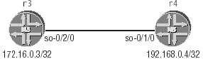
Figure 2.1: POS interface connecting r3 and r4
Physical Properties for POS Interfaces
The physical device properties of a POS interface determine its clocking, framing, CRC length, link-level encapsulation, and various other SONET parameters. A typical POS interface configuration could involve one or more of the following physical device criteria, which we will use in our example:
-
32-bit FCS (CRC)
-
Payload scrambling enabled
-
MTU of 4474 bytes
-
SDH framing, path trace set to "JNCIP test bed"
-
Internal timing
-
Cisco HDLC encapsulation with 5-second keepalives
-
Hold setting of 20 milliseconds
The following capture shows some of the default parameters for a POS interface on an M-series router. Based on this display, it is clear that additional device configuration will be needed to meet all of the criteria listed previously.
[edit interfaces so-0/2/0] lab@r3# run show interfaces so-0/2/0 Physical interface: so-0/2/0, Enabled, Physical link is Up Interface index: 16, SNMP ifIndex: 19 Link-level type: PPP, MTU: 4474, Clocking: Internal, SONET mode, Speed: OC3, Loopback: None, FCS: 16, Payload scrambler: Enabled Device flags : Present Running Interface flags: Point-To-Point SNMP-Traps Link flags : Keepalives Input rate : 0 bps (0 pps) Output rate : 0 bps (0 pps) SONET alarms : None SONET defects : None
This capture indicates that the default encapsulation of PPP (Point-to-Point Protocol) will need to be changed, as will the default 16-bit FCS (CRC) length and SONET framing mode.
Configuring POS Interface Physical Properties
The following commands configure the physical properties of r3’s so-0/2/0 POS interface in accordance with the criteria listed previously:
[edit interfaces so-0/2/0] lab@r3# set sonet-options fcs 32 [edit interfaces so-0/2/0] lab@r3# set sonet-options path-trace "JNCIP test bed" [edit interfaces so-0/2/0] lab@r3# set hold-time up 20 [edit interfaces so-0/2/0] lab@r3# set hold-time down 20 [edit interfaces so-0/2/0] lab@r3# set encapsulation cisco-hdlc [edit interfaces so-0/2/0] lab@r3# set keepalives interval 5
This configuration, combined with the interface’s default parameters, achieves all of the required configuration parameters with the exception of the need for SDH framing. Though rather unintuitive, the framing mode used for all the ports associated with a given SONET PIC is configured at the [edit chassis] hierarchy, as shown next:
[edit] lab@r3# set chassis fpc 0 pic 2 framing sdh
The completed physical configuration of r3’s so-0/2/0 POS interface is shown next:
[edit] lab@r3# show interfaces so-0/2/0 keepalives interval 5; hold-time up 20 down 20; encapsulation cisco-hdlc; sonet-options { fcs 32; path-trace "JNCIP test bed"; } [edit] lab@r3# show chassis fpc 0 pic 2 { framing sdh; } The results of a show interfaces extensive for r3’s so-0/2/0 interface is displayed next. The following capture has been edited for brevity:
lab@r3> show interfaces so-0/2/0 extensive Physical interface: so-0/2/0, Enabled, Physical link is Up Interface index: 16, SNMP ifIndex: 19, Generation: 19 Link-level type: Cisco-HDLC, MTU: 4474, Clocking: Internal, SDH mode, Speed: OC3, Loopback: None, FCS: 32, Payload scrambler: Enabled Device flags : Present Running Interface flags: Point-To-Point SNMP-Traps Link flags : Keepalives Hold-times : Up 20 ms, Down 20 ms Statistics last cleared: Never Traffic statistics: . . . Input errors: . . . Output errors: . . . SONET alarms : None SONET defects : None SONET PHY: Seconds Count State PLL Lock 0 0 OK PHY Light 0 0 OK SONET section: . . . SONET line: . . . 0 SONET path: . . . 0 Received SDH overhead: . . . Transmitted SDH overhead: . . . Received path trace: 00 00 00 00 00 00 00 00 00 00 00 00 00 00 00 00 ................ Transmitted path trace: JNCIP test bed 4a 4e 43 49 45 20 74 65 73 74 20 62 65 6g4 00 00 JNCIP test bed.. HDLC configuration: Policing bucket: Disabled Shaping bucket : Disabled Giant threshold: 4486, Runt threshold: 5 . . .
| Note | According to current JUNOS software documentation, the interface hold time can range from 0 (the default) to 65,535 milliseconds, with the configured value being rounded up to the nearest whole second. Therefore, any hold-time setting between 1 and 1000 inclusive should produce the same 1-second interface transition hold-down. |
The lack of the correct value for the received path trace value in the previous capture indicates that r4’s so-0/1/0 POS interface has not been configured with compatible SONET framing. By default, path trace information should contain the router’s host and transmitting interface name but instead r3 is showing null values for the received path trace. After configuring r4’s so-0/1/0 interface with identical parameters to those of r3, the received path trace displays the expected value:
[edit] lab@r3# run show interfaces so-0/2/0 extensive | match "path trace" Received path trace: JNCIP test bed Transmitted path trace: JNCIP test bed
Logical Properties of POS Interfaces
With the POS interface’s physical properties correctly set, it is time to move on to configuring the interface’s logical properties. Logical interface properties will normally involve the creation of logical units, the assignment of protocol families to these logical units, and the configuration of parameters associated with each particular protocol family as needed.
Configuring POS Interface Logical Properties
Typical configuration criteria for the logical properties of a POS interface might take the following form:
-
Logical unit 0
-
IPv4 family, MTU = 1600 bytes
-
Address assignment based on Table 2.2
| Router | POS Interface Address |
|---|---|
| r3 | 172.16.0.3/32 |
| r4 | 192.168.0.4/32 |
The only tricky part to this configuration assignment is the use of 32-bit host addresses on each end of the POS link, which creates two independent IP subnets that in turn require the use of the destination keyword to explicitly specify the address of the remote device. This is required in order to accommodate the proper routing of packets across the point-to-point link. The following commands correctly configure the logical properties of r3’s POS interface:
[edit interfaces so-0/2/0 unit 0 family inet] lab@r3# set mtu 1600 [edit interfaces so-0/2/0 unit 0 family inet] lab@r3# set address 172.16.0.3 destination 192.168.0.4 [edit interfaces so-0/2/0 unit 0 family inet] lab@r3# show mtu 1600; address 172.16.0.3/32 { destination 192.168.0.4; }
Verifying POS Interface Operation
When r4’s POS interface is correctly configured, you should be able to conduct ping testing to verify IP forwarding across the POS link. We begin our interface verification by confirming the POS interface is up at both the administrative and logical levels using the following command:
lab@r3> show interfaces so-* terse Interface Admin Link Proto Local Remote so-0/2/0 up up so-0/2/0.0 up up inet 172.16.0.3 --> 192.168.0.4 so-0/2/1 up down so-0/2/2 up down
The resulting display indicates that r3’s so-0/2/0 interface is administratively enabled, and that it is operational at the logical link layer, which in this example indicates that cisco-hdlckeepalives are being exchanged across the link. The presence of a configured logical unit on the POS interface also allows us to verify the correct setting of the keepalive timers:
lab@r3> show interfaces so-0/2/0 Physical interface: so-0/2/0, Enabled, Physical link is Up Interface index: 16, SNMP ifIndex: 19 Link-level type: Cisco-HDLC, MTU: 4474, Clocking: Internal, SDH mode, Speed: OC3, Loopback: None, FCS: 32, Payload scrambler: Enabled Device flags : Present Running Interface flags: Point-To-Point SNMP-Traps Link flags : Keepalives Keepalive settings: Interval 5 seconds, Up-count 1, Down-count 3 Keepalive: Input: 1 (00:00:00 ago), Output: 0 (never) Input rate : 88 bps (0 pps) Output rate : 0 bps (0 pps) SONET alarms : None SONET defects : None Logical interface so-0/2/0.0 (Index 4) (SNMP ifIndex 29) Flags: Point-To-Point SNMP-Traps Encapsulation: Cisco-HDLC Protocol inet, MTU: 1600, Flags: None Addresses, Flags: Is-Preferred Is-Primary Destination: 192.168.0.4, Local: 172.16.0.3
We now conduct a ping test to verify proper packet routing between r3 and r4:
lab@r3> ping 192.168.0.4 size 1540 PING 192.168.0.4 (192.168.0.4): 1540 data bytes 1548 bytes from 192.168.0.4: icmp_seq=0 ttl=255 time=2.548 ms 1548 bytes from 192.168.0.4: icmp_seq=1 ttl=255 time=2.435 ms ^C --- 192.168.0.4 ping statistics --- 2 packets transmitted, 2 packets received, 0% packet loss round-trip min/avg/max/stddev = 2.435/2.492/2.548/0.056 ms
Things look very good so far. Now for a flood ping stress test evoked with the rapid option:
lab@r3> ping rapid count 200 192.168.0.4 size 1540 PING 192.168.0.4 (192.168.0.4): 1540 data bytes !!!!!!!!!!!!!!!!!!!!!!!!!!!!!!!!!!!!!!!!!!!!!!!!!!!!!!!!!!!!!!!!!!!!!!!!!!!!!!!! !!!!!!!!!!!!!!!!!!!!!!!!!!!!!!!!!!!!!!!!!!!!!!!!!!!!!!!!!!!!!!!!!!!!!!!!!!!!!!!! !!!!!!!!!!!!!!!!!!!!!!!!!!!!!!!!!!!!!!! --- 192.168.0.4 ping statistics --- 200 packets transmitted, 200 packets received, 0% packet loss round-trip min/avg/max/stddev = 2.266/2.355/9.730/0.613 m
Based on these results, it would seem that congratulations on the successful configuration of a cisco-hdlc encapsulated POS interface are in order! In the next section, we will explore the remaining encapsulation options that are available for POS interfaces.
Encapsulation Options for POS Interfaces
A POS interface can be configured to operate with either the Cisco version of HDLC, Frame Relay, or PPP-based encapsulation. The use of cisco-hdlc (as illustrated in the previous section) is generally considered to be the most straightforward encapsulation approach because it supports very little in the way of configurable options. This section details common configuration requirements and testing techniques for Frame Relay and PPP encapsulations.
Configuring Frame Relay
The configuration of Frame Relay encapsulation requires the configuration of the frame-relay encapsulation type and the assignment of one or more DLCIs. In some cases, you may also have to modify the default data terminal equipment (DTE) line appearance and make modifications to the PVC management protocol parameters, depending on the network particulars that you need to accommodate. The PVC management protocol is often referred to as the Local Management Interface (LMI).
Running Frame Relay devices back-to-back requires that special attention be paid to the device type and keepalive settings because the default Frame Relay parameters will cause back- to-back connections to be declared down due to LMI keepalive malfunctions caused by the pairing of two Frame Relay DTEs. Also, the DLCI value must be the same at both ends of a back- to-back connection, because there will be no Frame Relay switch present to provide DLCI translation functions.
Typical Frame Relay configuration tasks are listed next. For simplicity, the same addressing and POS parameters used in the previous Cisco HDLC example will be retained in this example:
-
Use DLCI 100
-
Use the ITU Annex A version of PVC management protocol (LMI)
-
Keepalive parameters:
-
DTE poll interval 5 seconds, full status every poll
-
Set a line up/down threshold of 2/3 events
-
Though not explicitly specified in the task listing, the requirement that keepalives be enabled forces you to configure one or both of the routers to operate as a Frame Relay DCE (data communications equipment) because pairing two DTEs will force you to disable PVC management protocol–based keepalives.
| Note | Two DCE devices would be paired to create a network-to-network interface (NNI) with bi-directional keepalives enabled by the inclusion of the keepalives keyword at the physical-device level. |
This example begins by demonstrating the problems encountered with back-to-back Frame Relay DTE, and then moves on to show how these problems can be resolved by configuring one end of the link as a DCE. Because most of the keepalive parameters are dependent upon a device’s status as either a DTE or DCE, the keepalive parameters will be configured after demonstrating the problems with DTE-DTE connections.
We begin r3’s Frame Relay configuration by deleting the keepalive settings previously configured under keepalives. Frame Relay encapsulation has a unique set of LMI parameters that provide keepalive functionality:
[edit interfaces so-0/2/0] lab@r3# delete keepalives
And now the initial Frame Relay configuration is performed:
[edit interfaces so-0/2/0] lab@r3# set encapsulation frame-relay [edit interfaces so-0/2/0] lab@r3# set lmi lmi-type itu [edit interfaces so-0/2/0] lab@r3# set unit 0 dlci 100
The results of these commands are highlighted next; it is assumed that you have issued the same set of commands and DLCI assignment of 100 on r4’s so-0/1/0 interface:
[edit interfaces so-0/2/0] lab@r3# show hold-time up 20 down 20; encapsulation frame-relay; lmi { lmi-type itu; } sonet-options { fcs 32; path-trace "JNCIP test bed"; } unit 0 { dlci 100; family inet { mtu 1600; address 172.16.0.3/32 { destination 192.168.0.4; } } } In this example, we have assigned DLCI 100 to the interface’s existing logical unit 0. You could have renamed or reassigned the logical unit to match the DLCI value, but a specific value for the logical unit is not a requirement in this example. The results of this basic Frame Relay configuration leave much to be desired, as the following captures demonstrate:
| Tip | Although many operators prefer to make interface unit numbers match the associated virtual connection identifiers, the unit 0 approach taken here has certain advantages, and is perfectly legal when an interface supports a single connection identifier and therefore requires only one logical unit. The use of non-zero unit numbers can cause problems if the operator forgets to explicitly include the correct unit number when placing the interface into a protocol such as OSPF or IS-IS. The use of unit 0 provides some relief in these cases, as the omission of a unit number will cause the default value of 0 to be assumed. |
[edit interfaces so-0/2/0] lab@r3# run show interfaces terse | match so-0/2/0 Interface Admin Link Proto Local Remote so-0/2/0 up down so-0/2/0.0 up down inet 172.16.0.3 --> 192.168.0.4
It would seem that our Frame Relay link is down. The following command provides additional information about the cause of the problem:
[edit interfaces so-0/2/0] lab@r3# run show interfaces so-0/2/0 Physical interface: so-0/2/0, Enabled, Physical link is Up Interface index: 16, SNMP ifIndex: 19 Link-level type: Frame-Relay, MTU: 4474, Clocking: Internal, SDH mode, Speed: OC3, Loopback: None, FCS: 32, Payload scrambler: Enabled Device flags : Present Running Interface flags: Link-Layer-Down Point-To-Point SNMP-Traps Link flags : Keepalives DTE ITU LMI settings: n391dte 6, n392dte 3, n393dte 4, t391dte 10 seconds LMI: Input: 20 (00:00:00 ago), Output: 20 (00:00:02 ago) Input rate : 0 bps (0 pps) Output rate : 0 bps (0 pps) SONET alarms : None SONET defects : None Logical interface so-0/2/0.0 (Index 4) (SNMP ifIndex 29) Flags: Device-Down Point-To-Point SNMP-Traps Encapsulation: FR-NLPID Input packets : 57 Output packets: 46 Protocol inet, MTU: 1600, Flags: None Addresses, Flags: Dest-route-down Is-Preferred Is-Primary Destination: 192.168.0.4, Local: 172.16.0.3 DLCI 100 Flags: Active Total down time: 0 sec, Last down: Never Traffic statistics: Input packets: 57 Output packets: 46
Besides getting additional confirmation that the line is down, the show interfaces command provides a clue as to the nature of the problem. The LMI: portion of the display clearly indicates that LMI messages are being sent (Output) and received (Input), but despite this fact the line protocol remains down. A situation like this provides a strong indication that some type of incompatibility is causing the LMI messages to be ignored, because bit errors resulting from device malfunctions or device-level configuration mistakes would simply result in the discard of the corrupted messages causing the input/output counters to remain frozen. Before leaving this capture, take note of the default values for the LMI timers. To meet the requirements of this example, we will need to modify some of these timer values. The use of monitor traffic (tcpdump) will often provide you with important clues when you encounter interface problems. The following capture illustrates how traffic monitoring can be used in this example:
[edit interfaces so-0/2/0] lab@r3# run monitor traffic interface so-0/2/0 Listening on so-0/2/0 16:36:33.972435 In Call Ref: 75, MSG Type: 95 LOCK-SHIFT-5 IE: 01 Len: 1, LINK VERIFY IE: 03 Len: 2, TX Seq: 175, RX Seq: 49 16:36:35.883477 Out Call Ref: 75, MSG Type: 51 ITU LMI IE: 01 Len: 1, LINK VERIFY IE: 03 Len: 2, TX Seq: 145, RX Seq: 10 16:36:45.283870 Out Call Ref: 75, MSG Type: 51 ITU LMI IE: 01 Len: 1, LINK VERIFY IE: 03 Len: 2, TX Seq: 146, RX Seq: 10 16:36:45.672869 In Call Ref: 75, MSG Type: 95 LOCK-SHIFT-5 IE: 01 Len: 1, LINK VERIFY IE: 03 Len: 2, TX Seq: 176, RX Seq: 49 ^C 5 packets received by filter 0 packets dropped by kernel
These results indicate that both ends are generating status enquiries (message type 75), and that neither end is receiving a status message (message type 7D), which makes perfect sense when one recalls that the Frame Relay DCE device generates status messages in response to the receipt of a DTE-generated status enquiry. Also of interest in this capture is the fact that we have uncovered a configuration error on r4. The LMI messages sent from r4 are using the ANSI Annex D version of LMI, as indicated by the locking code-shift to national code set #5, which is not used in the ITU Q.933 Annex A version of the protocol. Because this example requires the use of ITU Annex A, we should consider ourselves lucky for catching this while there is still time for corrective action.
Now that we know the back-to-back pairing of Frame Relay DTEs has caused our problem, we can easily resolve the issue by configuring one of the routers as a DCE. In this case, we configure r4 as a DCE with the following commands (the incorrect LMI type is also corrected at this time):
[edit interfaces so-0/1/0] lab@r4# set dce [edit interfaces so-0/1/0] lab@r4# set lmi lmi-type itu
After committing these changes, we once again monitor the LMI exchanges between r3 and r4:
[edit interfaces so-0/2/0] lab@r3# run monitor traffic interface so-0/2/0 Listening on so-0/2/0 16:44:42.704152 Out Call Ref: 75, MSG Type: 51 ITU LMI IE: 01 Len: 1, LINK VERIFY IE: 03 Len: 2, TX Seq: 195, RX Seq: 13 16:44:42.704771 In Call Ref: 7d, MSG Type: 51 ITU LMI IE: 01 Len: 1, LINK VERIFY IE: 03 Len: 2, TX Seq: 14, RX Seq: 195 16:44:51.204457 Out Call Ref: 75, MSG Type: 51 ITU LMI IE: 01 Len: 1, LINK VERIFY IE: 03 Len: 2, TX Seq: 196, RX Seq: 14 16:44:51.205068 In Call Ref: 7d, MSG Type: 51 ITU LMI IE: 01 Len: 1, LINK VERIFY IE: 03 Len: 2, TX Seq: 15, RX Seq: 196 16:45:02.604939 Out Call Ref: 75, MSG Type: 51 ITU LMI IE: 01 Len: 1, LINK VERIFY IE: 03 Len: 2, TX Seq: 197, RX Seq: 15 16:45:02.605571 In Call Ref: 7d, MSG Type: 51 ITU LMI IE: 01 Len: 1, LINK VERIFY IE: 03 Len: 2, TX Seq: 16, RX Seq: 197 16:45:12.105339 Out Call Ref: 75, MSG Type: 51 ITU LMI IE: 01 Len: 1, FULL STATUS IE: 03 Len: 2, TX Seq: 198, RX Seq: 16 16:45:12.105965 In Call Ref: 7d, MSG Type: 51 ITU LMI IE: 01 Len: 1, FULL STATUS IE: 03 Len: 2, TX Seq: 17, RX Seq: 198 IE: 57 Len: 3, DLCI 100: status Active ^C 8 packets received by filter 0 packets dropped by kernel
The above results indicate the correct operation of the Frame Relay LMI protocol, as both link verify (keepalive) and DLCI status messages are being exchanged between r3 and r4. It is interesting to note that these results indicate that the LMI protocol is operating with the default settings of a 10-second poll interval with a full status exchange occurring every six polls (or once a minute). These parameters must now be adjusted to comply with the configuration requirements of this example. We begin by configuring the DTE device (r3) with the correct LMI parameters using the following commands:
[edit interfaces so-0/2/0] lab@r3# set lmi t391dte 5 [edit interfaces so-0/2/0] lab@r3# set lmi n391dte 1 [edit interfaces so-0/2/0] lab@r3# set lmi n392dte 2 [edit interfaces so-0/2/0] lab@r3# set lmi n393dte 3
The resulting configuration tells r3 to generate polls every five seconds (t391), to request full status with every poll (n391), and that it should consider the link down if two errors occur in any three monitored events (n392/n393). The resulting Frame Relay configuration for r3, our DTE, is shown next, with newly configured parameters highlighted:
lab@r3# show hold-time up 20 down 20; encapsulation frame-relay; lmi { n391dte 1; n392dte 2; n393dte 3; t391dte 5; lmi-type itu; } sonet-options { fcs 32; path-trace "JNCIP test bed"; } unit 0 { dlci 100; family inet { mtu 1600; address 172.16.0.3/32 { destination 192.168.0.4; } } } You must now enter the following commands on r4, which is functioning as the Frame Relay DCE:
[edit interfaces so-0/1/0] lab@r4# set lmi n392dce 2 [edit interfaces so-0/1/0] lab@r4# set lmi n393dce 3
| Note | The DCE maintains a poll expectation timer, T392, which must be set higher than the DTE’s T391 poll timer for reliable operation. If these two values are set to the same value, the result will likely be a line that oscillates between the up and down states at periodic intervals. Since the default value for T392 is 15 seconds, it will require modification only when the DTE’s T391 timer is set to a value greater than the default setting of 10. |
The resulting DCE configuration from r4, with Frame Relay–related portions highlighted, is shown next:
[edit interfaces so-0/1/0] lab@r4# show dce; hold-time up 20 down 20; encapsulation frame-relay; lmi { n392dce 2; n393dce 3; lmi-type itu; } sonet-options { fcs 32; path-trace "JNCIP test bed"; } unit 0 { dlci 100; family inet { mtu 1600; address 192.168.0.4/32 { destination 172.16.0.3; } } }
Verify Frame Relay
Once the configuration of both routers is complete, you can verify proper operation with ping testing. To confirm the settings of the LMI protocol, you can show the interface’s parameters, or monitor the protocol’s operation with monitor traffic as shown in the following examples:
lab@r3> show interfaces so-0/2/0 Physical interface: so-0/2/0, Enabled, Physical link is Up Interface index: 16, SNMP ifIndex: 19 Link-level type: Frame-Relay, MTU: 4474, Clocking: Internal, SDH mode, Speed: OC3, Loopback: None, FCS: 32, Payload scrambler: Enabled Device flags : Present Running Interface flags: Point-To-Point SNMP-Traps Link flags : Keepalives DTE ITU LMI settings: n391dte 1, n392dte 2, n393dte 3, t391dte 5 seconds LMI: Input: 322 (00:00:03 ago), Output: 324 (00:00:03 ago) Input rate : 0 bps (0 pps) Output rate : 0 bps (0 pps) SONET alarms : None SONET defects : None Logical interface so-0/2/0.0 (Index 4) (SNMP ifIndex 29) Flags: Point-To-Point SNMP-Traps Encapsulation: FR-NLPID Input packets : 59 Output packets: 48 Protocol inet, MTU: 1600, Flags: None Addresses, Flags: Is-Preferred Is-Primary Destination: 192.168.0.4, Local: 172.16.0.3 DLCI 100 Flags: Active Total down time: 0 sec, Last down: Never Traffic statistics: Input packets: 59 Output packets: 48
The results of a show interfaces are as expected. The link is up and the counters indicate the transmission and reception of LMI-related messages. We now monitor traffic to confirm the specifics of LMI protocol operation:
lab@r3> monitor traffic interface so-0/2/0 Listening on so-0/2/0 17:16:17.584353 Out Call Ref: 75, MSG Type: 51 ITU LMI IE: 01 Len: 1, FULL STATUS IE: 03 Len: 2, TX Seq: 154, RX Seq: 227 17:16:17.584972 In Call Ref: 7d, MSG Type: 51 ITU LMI IE: 01 Len: 1, FULL STATUS IE: 03 Len: 2, TX Seq: 228, RX Seq: 154 IE: 57 Len: 3, DLCI 100: status Active 17:16:21.384512 Out Call Ref: 75, MSG Type: 51 ITU LMI IE: 01 Len: 1, FULL STATUS IE: 03 Len: 2, TX Seq: 155, RX Seq: 228 17:16:21.385131 In Call Ref: 7d, MSG Type: 51 ITU LMI IE: 01 Len: 1, FULL STATUS IE: 03 Len: 2, TX Seq: 229, RX Seq: 155 IE: 57 Len: 3, DLCI 100: status Active
Very nice! The time stamps and message contents indicate that we now have full status exchanges with every poll, and that polls are occurring every five seconds. This behavior demonstrates that, based on the requirements given for this configuration example, we have correctly configured a POS interface with Frame Relay encapsulation.
Point-to-Multipoint Frame Relay Connections
The previous Frame Relay examples have demonstrated point-to-point connection types. You should also be able to configure point-to-multipoint connections to create a non-broadcast multi-access (NMBA) topology as needed. Inverse ARP (IN-ARP) is often deployed on multi- point connections to eliminate the need for the manual mapping of local DLCI values to remote IP addresses. As of this writing, JUNOS software does not offer full IN-ARP support for Frame Relay or ATM interfaces. While an M-series router can be configured to respond to IN-ARP requests (as might be sent from another vendor’s router), the Juniper Networks router cannot generate IN-ARP requests. As a result, you will need to manually configure all DLCI to remote IP address mappings when configuring multipoint connections with JUNOS software. IN-ARP response support can be configured on non–Juniper Networks equipment to eliminate the need for static mappings as desired.
The following example is based on the topology shown in Figure 2.2. Here, r1 is connected through a Frame Relay network to r2 and r3 using its so-0/0/0 interface. All routers in this example have been configured with a common IP subnet of 10.0.1/24, which represents the WAN cloud.
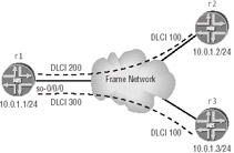
Figure 2.2: Multipoint Frame Relay connections
The following commands correctly configure r1 for this multipoint, NMBA application. Use of the multipoint keyword to support this application is worth noting:
[edit interfaces so-0/0/0] lab@r1# set encapsulation frame-relay lab@r1# set unit 0 multipoint [edit interfaces so-0/0/0] lab@r1# set unit 0 family inet address 10.0.1.1/24 [edit interfaces so-0/0/0 unit 0 family inet address 10.0.1.1/24] lab@r1# set multipoint-destination 10.0.1.2 dlci 200 [edit interfaces so-0/0/0 unit 0 family inet address 10.0.1.1/24] lab@r1# set multipoint-destination 10.0.1.3 dlci 300 [edit interfaces so-0/0/0 unit 0 family inet address 10.0.1.1/24] lab@r1# up 3 [edit interfaces so-0/0/0] lab@r1# show encapsulation frame-relay; unit 0 { multipoint; family inet { address 10.0.1.1/24 { multipoint-destination 10.0.1.2 dlci 200; multipoint-destination 10.0.1.3 dlci 300; } } } The key aspects of this multipoint configuration are the inclusion of the multipoint keyword and the static DLCI to IP mappings configured as arguments to the multipoint-destination keyword. If the remote routers (r3 and r2) have been configured for dynamic address mappings (IN-ARP support), then you must also include support for IN-ARP replies on r1 as shown in the following:
[edit interfaces so-0/0/0] lab@r1# set unit 0 inverse-arp [edit interfaces so-0/0/0] lab@r1# show encapsulation frame-relay; unit 0 { multipoint; inverse-arp; family inet { address 10.0.1.1/24 { multipoint-destination 10.0.1.2 dlci 200; multipoint-destination 10.0.1.3 dlci 300; } } }
Configuring PPP
JUNOS software supports PPP encapsulation on POS interfaces, but does not support many of the enhanced capabilities of PPP because of the lack of support for switched connections and the limited protocol support needed by a core IP router. The support of a limited subset of the PPP’s capabilities makes the configuration of PPP relatively easy on an M-series router. Figure 2.3 shows the sample topology that will be used to demonstrate PPP configuration and interface verification.
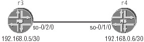
Figure 2.3: PPP topology
Because r3 and r4 share a common /30 subnet in this example, the destination keyword is not needed for proper routing across the point-to-point link. The following commands delete the existing interface configuration and correctly configure r3’s so-0/2/0 interface for basic PPP operation:
[edit interfaces so-0/2/0] lab@r3# delete Delete everything under this level? [yes,no] (no) yes [edit interfaces so-0/2/0] lab@r3# set unit 0 family inet address 192.168.0.5/30 lab@r3# show unit 0 { family inet { address 192.168.0.5/30; } } Because PPP is by nature a point-to-point protocol, only one logical unit can be configured for a PPP-encapsulated interface and this logical unit must be unit 0. Also, because PPP encapsulation is the default encapsulation for POS interfaces, there is no need to explicitly configure the interface’s encapsulation when basic PPP functionality is required.
Verifying PPP
The PPP transitions through various states before the interface becomes operational at the network layer (dead, link up, authentication, LCP open, and ultimately network control protocol [NCP] open for each configured protocol family). Configuration problems and incompatibilities can result in the PPP becoming stuck in a particular state. Knowing how PPP progresses through these various states and being able to determine that it is hung at a particular phase can greatly simplify PPP troubleshooting.
PPP makes use of a Link Control Protocol (LCP) to provide keepalive and link-level negotiation functions such as PPP address and control field compression. Generally speaking, problems with LCP establishment indicate hardware or transmission link problems, but can also be caused by incompatible LCP settings between the devices that terminate the link. At the time of this writing, JUNOS software does not support the configuration of LCP-related options such as address or control field compression, so the correction of any incompatibilities that arise will require the modification of the non–Juniper Networks device’s settings.
Information on the state of the PPP can be obtained by viewing the interface, as shown next:
[edit interfaces so-0/2/0] lab@r3# run show interfaces so-0/2/0 Physical interface: so-0/2/0, Enabled, Physical link is Up Interface index: 16, SNMP ifIndex: 19 Link-level type: PPP, MTU: 4474, Clocking: Internal, SDH mode, Speed: OC3, Loopback: None, FCS: 16, Payload scrambler: Enabled Device flags : Present Running Interface flags: Point-To-Point SNMP-Traps Link flags : Keepalives Keepalive settings: Interval 10 seconds, Up-count 1, Down-count 3 Keepalive: Input: 97 (00:00:08 ago), Output: 97 (00:00:02 ago) LCP state: Opened NCP state: inet: Opened, inet6: Not-configured, iso: Not-configured, mpls: Not-configured Input rate : 40 bps (0 pps) Output rate : 48 bps (0 pps) SONET alarms : None SONET defects : None Logical interface so-0/2/0.0 (Index 4) (SNMP ifIndex 29) Flags: Point-To-Point SNMP-Traps Encapsulation: PPP Protocol inet, MTU: 4470, Flags: None Addresses, Flags: Is-Preferred Is-Primary Destination: 192.168.0.4/30, Local: 192.168.0.5
From this display, you can see that the LCP has been correctly opened, and that it is exchanging keepalives across the link. Furthermore, we can see that the IPv4 Control Protocol (IPCP) connection has successfully entered the opened state, while the NCP connections for MPLS and ISO have not been opened because these protocol families have not been configured on the logical interface. The operation of PPP can also be verified through the use of traffic monitoring as shown in the following example:
[edit interfaces so-0/2/0] lab@r3# run monitor traffic interface so-0/2/0 Listening on so-0/2/0 11:10:12.830818 Out LCP echo request (type 0x09 id 0x88 len 0x0008) 11:10:12.831422 In LCP echo reply (type 0x0a id 0x88 len 0x0008) 11:10:18.776802 In LCP echo request (type 0x09 id 0x7a len 0x0008) 11:10:18.776817 Out LCP echo reply (type 0x0a id 0x7a len 0x0008) 11:10:20.731145 Out LCP echo request (type 0x09 id 0x89 len 0x0008) 11:10:20.731749 In LCP echo reply (type 0x0a id 0x89 len 0x0008) ^C 6 packets received by filter 0 packets dropped by kernel
The resulting output shows that bidirectional keepalives are being sent, which confirms that LCP is open and that the data link is capable of passing traffic. In the following capture, one end of the link is deactivated while the results are monitored at r3:
[edit interfaces so-0/2/0] lab@r3# run monitor traffic interface so-0/2/0 Listening on so-0/2/0 11:13:04.582841 In LCP echo request (type 0x09 id 0x8b len 0x0008) 11:13:04.582849 Out LCP echo reply (type 0x0a id 0x8b len 0x0008) 11:13:12.648573 In IPCP terminate request (type 0x05 id 0x8c len 0x0004) 11:13:12.648649 Out IPCP terminate acknowledge (type 0x06 id 0x8c len 0x0004) 11:13:12.692233 In LCP terminate request (type 0x05 id 0x8d len 0x0004) 11:13:12.692246 Out LCP terminate acknowledge (type 0x06 id 0x8d len 0x0004) 11:13:14.688520 Out LCP configure request (type 0x01 id 0x9a len 0x000a) LCP OPTION: Magic number (type 0x05 len 0x06 val 0x3cbdb0ac) . . .
Here you can see that r4 initiates the teardown of the IP control protocol, and then follows up by tearing down the LCP session. After acknowledging r4’s request for IPCP and LCP termination, r3 then tries to reestablish the link by generating LCP configure requests. The magic number option is used to provide loopback detection, and cannot be disabled in JUNOS software. LCP echoes will not be sent if keepalives are disabled with the no-keepalives option, but the LCP will still be opened to facilitate the operation of the various NCPs needed to support the configured protocol families.
Using CHAP Authentication
Though PPP authentication using the Password Authentication Protocol (PAP) or Challenge Handshake Authentication Protocol (CHAP) is normally associated with switched connections, recent versions of JUNOS software include support for the CHAP authentication option. To configure CHAP on a PPP interface, issue the following commands with the appropriate variables as needed for the specifics of your configuration:
[edit interfaces so-0/2/0] lab@r3# set interfaces so-0/2/0 encapsulation ppp [edit interfaces so-0/2/0 ppp-options] lab@r3# set chap local-name r3 access-profile test [edit interfaces so-0/2/0] lab@r3# top lab@r3# set access profile test client r4 chap-secret jni
The modified configuration is shown next with the CHAP and authentication-related options highlighted. PPP encapsulation must be explicitly configured before the operator can commit a configuration that makes use of ppp-options, even though PPP encapsulation is the default:
[edit] lab@r3# show interfaces so-0/2/0 encapsulation ppp; ppp-options { chap { access-profile test; local-name r3; } } unit 0 { family inet { address 192.168.0.5/30; } } lab@r3# show access profile test { client r4 chap-secret "$9$a7GjqCA0BIc"; # SECRET-DATA } Because r4 has not yet been configured for CHAP authentication, we now have a link layer incompatibility that results in PPP getting stuck at the LCP open stage:
[edit] lab@r3# run show interfaces so-0/2/0 Physical interface: so-0/2/0, Enabled, Physical link is Up Interface index: 16, SNMP ifIndex: 19 Link-level type: PPP, MTU: 4474, Clocking: Internal, SDH mode, Speed: OC3, Loopback: None, FCS: 16, Payload scrambler: Enabled Device flags : Present Running Interface flags: Point-To-Point SNMP-Traps Keepalive settings: Interval 10 seconds, Up-count 1, Down-count 3 Keepalive: Input: 0 (never), Output: 0 (never) LCP state: Conf-ack-sent NCP state: inet: Down, inet6: Not-configured, iso: Not- configured, mpls: Not- configured Input rate : 104 bps (0 pps) Output rate : 136 bps (0 pps) SONET alarms : None SONET defects : None Logical interface so-0/2/0.0 (Index 4) (SNMP ifIndex 29) Flags: Hardware-Down Point-To-Point SNMP-Traps Encapsulation: PPP Protocol inet, MTU: 4470, Flags: Protocol-Down Addresses, Flags: Dest-route-down Is-Preferred Is-Primary Destination: 192.168.0.4/30, Local: 192.168.0.5
Traffic monitoring on r3 provides useful clues in this case:
lab@r3# run monitor traffic interface so-0/2/0 Listening on so-0/2/0 11:52:25.730741 In LCP configure request (type 0x01 id 0x10 len 0x000a) LCP OPTION: Magic number (type 0x05 len 0x06 val 0x3cb67f61) 11:52:25.730767 Out LCP configure acknowledge (type 0x02 id 0x10 len 0x000a) LCP OPTION: Magic number (type 0x05 len 0x06 val 0x3cb67f61) . . . 11:52:28.738220 Out LCP configure request (type 0x01 id 0x81 len 0x000f) LCP OPTION: Magic number (type 0x05 len 0x06 val 0x3cbda343) LCP OPTION: Authentication protocol (type 0x03 len 0x05 val 0xc2 0x23 0x05 ) 11:52:28.738844 In LCP configure negative ack (type 0x03 id 0x81 len 0x0009) LCP OPTION: Authentication protocol (type 0x03 len 0x05 val 0xc2 0x23 0x05 ) ^C 6 packets received by filter 0 packets dropped by kernel
Here you can clearly see that r4’s configure requests (In LCP) do not contain the authentication option. However, the LCP configure requests sent from r3 (Out LCP) indicate a desire to use authentication. Because r4 has not been configured for CHAP, it refuses the LCP configure request received from r3, which results in a failure of the LCP open. After configuring r4 with CHAP authentication and a compatible secret, the PPP once again operates correctly as shown in the following:
1:58:56.975423 In LCP configure request (type 0x01 id 0x02 len 0x000f) LCP OPTION: Magic number (type 0x05 len 0x06 val 0x3cba6a6b) LCP OPTION: Authentication protocol (type 0x03 len 0x05 val 0xc2 0x23 0x05 ) 11:58:56.975502 Out LCP configure request (type 0x01 id 0x46 len 0x000f) LCP OPTION: Magic number (type 0x05 len 0x06 val 0x3cc218cf) LCP OPTION: Authentication protocol (type 0x03 len 0x05 val 0xc2 0x23 0x05 ) 11:58:56.975514 Out LCP configure acknowledge (type 0x02 id 0x02 len 0x000f) LCP OPTION: Magic number (type 0x05 len 0x06 val 0x3cba6a6b) LCP OPTION: Authentication protocol (type 0x03 len 0x05 val 0xc2 0x23 0x05 ) 11:58:56.976093 In LCP configure acknowledge (type 0x02 id 0x46 len 0x000f) LCP OPTION: Magic number (type 0x05 len 0x06 val 0x3cc218cf) LCP OPTION: Authentication protocol (type 0x03 len 0x05 val 0xc2 0x23 0x05 ) 11:58:56.976322 In 23 03 CHAP: Challenge, Value=209b2a49005365580e3dac339d484b42, Name=r4 0103 0017 1020 9b2a 4900 5365 580e 11:58:56.977101 Out 23 03 CHAP: Challenge, Value=6219ad3f7fa423050caefc3a1783da02, Name=r3 0147 0017 1062 19ad 3f7f a423 050c 11:58:56.977335 Out 23 03 CHAP: Response, Value=73d43645397ad22e0c4115765663b581, Name=r3 0203 0017 1073 d436 4539 7ad2 2e0c 11:58:56.977864 In 23 03 CHAP: Response, Value=d966a3b7137c35ad5f8b37267737aea8, Name=r4 0247 0017 10d9 66a3 b713 7c35 ad5f 11:58:56.977985 Out 4 03 CHAP: Success 0347 0004 11:58:56.978073 Out IPCP configure request (type 0x01 id 0x48 len 0x0004) 11:58:56.978099 In 4 03 CHAP: Success 0303 0004 11:58:56.978114 In IPCP configure request (type 0x01 id 0x04 len 0x0004) 11:58:56.978145 Out IPCP configure acknowledge (type 0x02 id 0x04 len 0x0004) 11:58:56.978699 In IPCP configure acknowledge (type 0x02 id 0x48 len 0x0004) 11:59:00.654824 Out LCP echo request (type 0x09 id 0x49 len 0x0008) 11:59:00.655441 In LCP echo reply (type 0x0a id 0x49 len 0x0008)
Summary of POS Interface Configuration
Packet over SONET (POS) interfaces can be configured to run point-to-point protocols such as Cisco HDLC or PPP, and can operate with Frame Relay encapsulation for multipoint capabilities. Care must be taken when configuring a back-to-back Frame Relay connection due to the nature of the LMI keepalive mechanism and the need for a DTE-DCE line discipline on the data link. By default, M-series routers will function as Frame Relay DTEs, so either keepalives have to be disabled or one of the devices will need to be configured as a DCE.
Verification of a POS interface can be performed through ping testing, showing the interface, or by monitoring the traffic on that interface.
|
|
EAN: 2147483647
Pages: 132