Special States

I l @ ve RuBoard

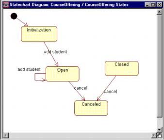
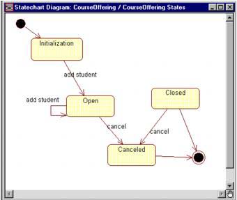
There are two special states that are added to the statechart diagram. The first is a start state. Each diagram must have one and only one start state since the object must be in a consistent state when it is created. The UML notation for a start state is a small solidfilled circle as shown in Figure 9-5. The second special state is a stop state. An object can have multiple stop states. The UML notation for a stop state is a bull's eye, as shown in Figure 9-5.

CREATING START STATES IN RATIONAL ROSE

graphics/quatranirose_icon.gif
  1. Click to select the Start icon from the toolbar.

  2. Click on the statechart diagram to draw the Start icon.

  3. Click to select the State Transition icon from the toolbar.

  4. Click on the Start icon and drag the arrow to the desired state.

Figure 9-5. UML Notation for Start and Stop States

graphics/09fig05.gif

A start state is shown in Figure 9-6.

CREATING STOP STATES IN RATIONAL ROSE

graphics/quatranirose_icon.gif
  1. Select the Stop icon from the toolbar.

  2. Click on the statechart diagram to draw the Stop icon.

  3. Select the State Transition icon from the bar.

  4. Click on the state and drag the arrow to the Stop icon.

Figure 9-6. Start State

graphics/09fig06.jpg

A stop state is shown in Figure 9-7.

Figure 9-7. Stop State

graphics/09fig07.jpg

I l @ ve RuBoard


Visual Modeling with Rational Rose 2002 and UML
Visual Modeling with Rational Rose 2002 and UML (3rd Edition)
ISBN: 0201729326
EAN: 2147483647
Year: 2002
Pages: 134

flylib.com © 2008-2017.
If you may any questions please contact us: flylib@qtcs.net