Use Case Relationships
| I l @ ve RuBoard |
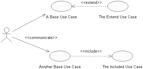
| An association relationship may exist between an actor and a use case. This type of association is often referred to as a communicate association since it represents communication between an actor and a use case. An association may be navigable in both directions (actor to use case and use case to actor) or it may be navigable in only one direction (actor to use case or use case to actor). The navigation direction of an association represents who is initiating the communication (i.e., the actor is initiating the communication with the use case, the use case is initiating the communication with the actor). An association is represented as a line connecting the related elements. Navigation in only one direction is depicted by adding an arrowhead to the association line that denotes the direction. There are two types of relationships that may exist between use cases: include and extend . Multiple use cases may share pieces of the same functionality. This functionality is placed in a separate use case rather than documenting it in every use case that needs it. Include relationships are created between the new use case and any other use case that "uses" its functionality. For example, each use case in the ESU Course Registration System starts with the verification of the user. This functionality can be captured in a User Verification use case, which is then used by other use cases as needed. An include relationship is drawn as a dependency relationship that points from the base use case to the used use case. An extend relationship is used to show
For example, a use case that monitors the flow of packages on a conveyer belt can be extended by a Trigger Alarm use case if the packages jam. At this time, no extensions have been identified for the ESU Course Registration System. An extend relationship is drawn as a dependency relationship that points from the extension to the base use case. The UML has a concept called a stereotype , which provides the capability of extending the basic modeling elements to create new elements. Thus, the concept of a stereotype allows the UML to have a minimal set of symbols that may be extended where needed to provide the communication artifacts that have meaning for the system under development. Stereotype names are included within guillemets (<< >>) and placed along the relationship line. Stereotypes are used to create the needed use case relationships. The stereotype <<communicate>> may be added to an association to show that the association is a communicate association. This is optional since an association is the only type of relationship allowed between an actor and a use case. Include and extend relationships must use stereotypes since they are both represented by a dependency relationship. Use case relationships are shown in Figure 3-9. Figure 3-9. Use Case Relationships |
| I l @ ve RuBoard |
EAN: 2147483647
Pages: 134
