The Implementation View
| I l @ ve RuBoard |
| This view of architecture concerns itself with the actual software module organization within the development environment. The implementation view of architecture takes into account derived requirements related to ease of development, software management, reuse, and constraints imposed by programming languages and development tools. The modeling elements in the component view of architecture are packages and components along with their connections. A package in this view of architecture represents a physical partitioning of the system. The packages are organized in a hierarchy of layers where each layer has a well-defined interface. The fact that an object-oriented system tends to be a layered system should not bring any surprises . This is due to the definition of an objectit should do one thing and do it well! A drawing showing some typical layers of a system may be found in Figure 11-3. Figure 11-3. System Layers The UML notation for a package in the component view is the same as a package in the logical viewa notched folder as found in Figure 11-4. CREATING COMPONENT VIEW PACKAGES IN RATIONAL ROSE
Figure 11-4. UML Notation for a Package The main component diagram typically is a view of the packages defined for the system. THE MAIN COMPONENT DIAGRAM IN RATIONAL ROSE
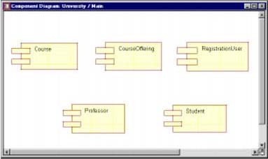
The main component diagram for the ESU Course Registration problem is shown in Figure 11-5. Figure 11-5. Main Component Diagram Source Code ComponentsIn the Component View of the model, a source code component represents a software file that is contained by a package. The type of file is language dependent (e.g., in C++, software components represent .h and .cpp files, in Java they represent .java files, and in PowerBuilder a software component is a .pbl). Each component is assigned a language that is discussed in the language-dependent appendixes. Classes in the Logical View are mapped to components in the Component view. In C++, the mapping is typically one-to-one; that is, one class maps to one component. However, there are times that more that one class will be mapped to a component. This is usually done when there is very tight coupling between the classes. For example, a container and its iterator are contained within one .h and one .cpp file. In this case, the container and the iterator classes would be mapped to one component. I have also seen classes that represent a pattern of collaboration mapped to one physical file. The UML notation for a component is shown in Figure 11-6. Figure 11-6. UML Notation for a Component Software Components in the ESU Course Registration ProblemThis is a relatively simple system and the decision was made to provide a one-to-one mapping between classes and componentseach class has its own header and .cpp file. CREATING COMPONENTS IN RATIONAL ROSE
A sample component diagram is shown in Figure 11-7. MAPPING CLASSES TO COMPONENTS IN RATIONAL ROSE
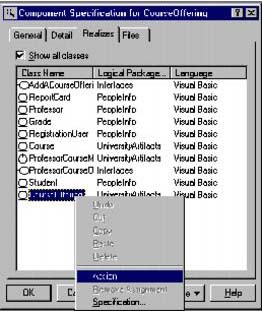
Figure 11-7. Software Components Note A class may also be assigned to a component by selecting it in the browser and dragging it onto the component (in the browser or on a component diagram). The Component Specification for the CourseOffering component is shown in Figure 11-8. Figure 11-8. Component Specification for the CourseOffering component |
| I l @ ve RuBoard |
EAN: 2147483647
Pages: 134