The Logical View
| I l @ ve RuBoard |
| This view of architecture addresses the functional requirements of the systemwhat the system should provide in terms of services to its users. The logical architecture is captured in class diagrams that contain the classes and relationships that represent the key abstractions of the system under development. Most of the UML notation that has been addressed so far is contained within this view of architecture (e.g., classes, associations, aggregations, generalization, and packages). This view of architecture is addressed early in the elaboration phase with the creation of classes and packages that represent the major abstractions of the domain. As time moves on, more classes and packages are added to the model to reflect the decisions made concerning the key mechanisms of the system. A key mechanism is a decision regarding common standards, polices, and practices. The selection of the key mechanisms for a system is often referred to as tactical design. "Poor tactical design can ruin even the most profound architecture, and so the team must mitigate this risk by explicitly identifying the project's key policies." [6] Some common key mechanisms involve the selection of an implementation language, persistent data storage, the look and feel of the user interface, error handling, communication mechanisms, object distribution and object migration, and networking.
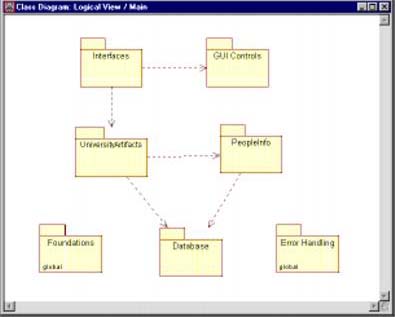
Today, many patterns exist that may be used to implement the key mechanism decisions made for your system. I strongly recommend looking into patterns before you try to "roll your own." Additionally, the concepts of cohesion, closure, and reuse will affect the choices that you make. Robert Martin discusses some of the ramifications of the choice of packages for your system in his book Designing Object-Oriented C++ Applications Using the Booch Method . Although this book uses the Booch notation and process, it is still applicable to the Rational Unified Process and the UML. The bottom line is this: The UML may be used to communicate the strategic decisions made for your system by adding packages and classes to the model to communicate, implement, and document these decisions. Sample Key Mechanisms for the ESU Course Registration ProblemSince most of the development team had prior experience using the C++ language and because this system eventually will be expanded to include other university functionality, C++ is the language of choice by the architecture team. The architecture team also decided that a particular set of graphical user interface (GUI) controls should be used to control the look and feel of the user interface, and therefore, a package called GUI Controls is added to the model. The database persistence strategy chosen by the architecture team is the use of a corresponding database class (shadow class) for each persistent class in the system. Although other strategies that mainly involve the use of inheritance could have been chosen by the team, this strategy was chosen due to the fact that expertise in implementing this method of persistence already existed and the team felt that it had the least amount of risk. A database package containing the shadow classes is added to the model at this time. Additionally, it was decided to make use of the C++ features of catch and throw for exceptions. Rather than have each class be responsible for knowing how to catch and throw exceptions, a package called Error Handling is added to the model. Finally, a set of commercial foundation classes was chosen for this system. The packages representing the key mechanism decisions made for the course registration system are shown in Figure 11-2. Figure 11-2. ESU Course Registration System Since the Error Handling package and the Foundations package are used by every other package in the system, they are global packages. MAKING A PACKAGE GLOBAL IN RATIONAL ROSE
|
| I l @ ve RuBoard |
EAN: 2147483647
Pages: 134