Basic Concepts of Kernel-Mode Drivers
| | ||
| | ||
| | ||
The material that covered in this section is generally considered difficult. Therefore, before you study it, I recommend that you achieve a proper understanding of page addressing (Chapter 19) and services programming (Chapter 21). When describing kernel-mode drivers, I will actively use material provided in these chapters.
Kernel-mode drivers that can operate only under operating systems of the Windows NT family should not be confused with Win32 Driver Model (WDM) drivers. WDM drivers can run under Windows 98, Windows 2000, and Windows XP because they are compatible at the level of binary code. This type of driver will not be covered here.
The Kernel and Memory Structure
First, it is necessary to define the operating system kernel. The kernel is part of the operating system stored in RAM. The kernel must be protected against any attempts at infringement (malicious or not) by application programs. It is impossible to ensure absolute kernel protection without hardware support. The protected mode of Intel processors provides such a support. In Chapter 19, I described the protected mode in relation to memory management. I hope that you have acquired basic knowledge about the protected mode. Review Fig. 19.4, which illustrates the address space of a process. The use of the paging mechanism allows you to achieve a wonderful effectthe address space significantly exceeds the real size of the physical memory. At the same time, the actual memory page might be stored in the so-called paging file instead of physical memory. This is an interesting effect; however, the limited space in this book prevents me from considering it in detail.
Intel processors simultaneously use two mechanisms of forming memory addresses. These are segment and page mechanisms. The page mechanism operates at a lower level. When it comes to protection, segment-level protection has higher priority than page-level protection. In other words, if a specific segment is assigned the highest privilege, this privilege will be in force regardless of the privilege levels set for the page level. On the other hand, if protection level 3 is set for the segment, then everything depends on the privilege level set for specific pages. There are only two privilege levels for pages0 and 3. In Windows, the so-called flat memory model is adopted. The selector that points to the segment descriptor starting at address 0 is loaded into segment registers. Because the offset within a segment is defined by a 32-bit value, this allows an address space of 4 GB. No other segments are assumed to exist in the system. This means that mere is only one vast segment. Well, then, where is the protection? The answer is straightforwardthe protection is implemented at the page level. Return to Fig. 19.4, where you'll see the memory region occupied by the operating system (to be more precise, occupied by its kernel, according to the definition provided earlier in this chapter). These pages are protected against access by normal executable modules, although they reside in the same address space. Also note that page memory organization allows you to protect the program code. Pages containing the program code are marked as read-only. In parallel to this, all mechanisms of segment addressing, such as gateways and interrupts, are operating, because they cannot be implemented at the page level. These operations are hidden from a normal program, which sees only the flat address space.
How is multitasking implemented? Here, the page table mechanism comes into action (see Fig. 19.3). The CR3 register contains the address of the page table directory. Every task has its individual directory of page tables. Thus, switching between tasks can be implemented by changing the contents of the CR3 register. The directory contents define the mapping of the virtual address space to physical resources of the computer. The most important point is that the operating system kernel is mapped to the address space of every task. The goal is to consider legal mechanisms that allow the driver (e.g., some software module) to start in the kernel mode and communicate to applications that have lower privileges. Kernel-mode drivers have great power over the operating system and the entire computer. First, they can directly access peripheral devices through input and output ports. Second, such drivers can directly call the operating system kernel code. These capabilities imply greater responsibility, because even the slightest error can crash the entire operating system, causing the "blue screen of death" to appear. This topic is the most interesting because now you are approaching the inner sanctum of the Windows operating system.
Controlling Drivers
However surprising this might seem, kernel-mode drivers are controlled according to the same method used for controlling services. In Chapter 21, I explained in detail how to proceed to install, configure, start, stop, and remove services. Kernel-mode drivers are controlled in exactly the same way. Thus, the programs presented in Chapter 21 can be used practically without changes. Recall that the program in Listing 21.1 represents the service text. Naturally, it won't be needed here. The program in Listing 21.2 carries out service installation, the program in Listing 21.3 starts the service, and the program in Listing 21.4 stops the service and deletes it from the system. Among these programs, only the program in Listing 21.2 requires considerable changes. These modifications relate to the CreateService function call. The following is the fragment illustrating how to use the Createservice function to install a kernel-mode driver:
PUSH 0 PUSH 0 PUSH 0 PUSH 0 PUSH 0 PUSH OFFSET NM PUSH SERVICE_ERROR_NORMAL PUSH SERVICE_DEMAND_START PUSH SERVICE_KERNEL_DRIVER PUSH SERVICE_START + DELETE ; Instead of SERVICE_ALL_ACCESS PUSH OFFSET SNAME1 PUSH OFFSET SNAME1 PUSH H1 CALL CreateServiceA@52
Also, I have changed some parameters. The list of constants that I used is as follows :
DELETE equ l0000h SERVICE_START equ 10h SERVICE_KERNEL_DRIVER equ 00000001h
Pay attention to the fifth parameter from the end. It specifies the service type, which in this case is SERVICE_KERNEL_DRIVER . This means that the program informs the service control manager that this program isn't a normal service but is a kernel-mode driver.
| Note | The service control program allowing you to control services in the interactive dialog mode is useless here. All manipulations with drivers can only be done programmatically. As relates to the system registry, all data related to drivers are stored under the same registry key as the service- related data: HKEY_LOCAL_MACHINE\SYSTEM\CurrentControlSet\Services Accordingly, if you delete all references to a specific driver from the registry, you'll remove that driver from the system. Nevertheless, you can view the list of drivers installed in the system using the MSINFO32.EXE program. If your driver has been correctly installed, you'll find it in the list displayed by this program. Fig. 27.1 shows the console window of this program. Unfortunately, this program doesn't provide any capabilities except viewing the list of installed drivers. |
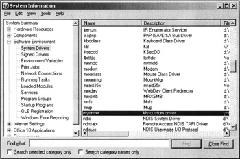
Figure 27.1: Console of the MSINFO32.EXE program allows you to view the list of drivers installed in the system
An Example of a Simple Kernel-Mode Driver
The goal of this section is to show you how to write the simplest kernel-mode driver, which would demonstrate the main capabilities of programs granted the highest privileges. I have chosen sound playback. To observe the purity of the experiment, I'll first try to reproduce the sound playback algorithm in a simple console application.
| |
.586P ; Flat memory model .MODEL FLAT, stdcall EXTERN ExitProcess@4:NEAR ;---------------------------------------------- ; INCLUDELIB directives for the linker includelib d:\masm32\lib\kernel32.lib ;---------------------------------------------- ; Data segment _DATA SEGMENT _DATA ENDS ; Code segment _TEXT SEGMENT START: ; Setting the write mode CLI MOV AL, 10110110B OUT 43H, AL IN AL, 61H ; Allow communication with the timer OR AL, 3 OUT 61H, AL MOV AX, 1200 ; Set the sound frequency ; The timer is triggered immediately ; after sending the counter value OUT 42H, AL MOV AL, AH OUT 42H, AL STI MOV ECX, 0FFFFFFH ; Delay LOO: LOOP LOO ; Detach the channel from the speaker, which means stop sound playback CLI IN AL, 61H AND AL, 11111100B OUT 61H, AL STI ;----------------------------- PUSH 0 CALL ExitProcess@4 _TEXT ENDS END START
| |
You can compile this console application in the usual way. It seems OK at first glance; however, when you start it, an error message will appear. Why does this happen? This program starts in ring 3, and the operating system informs you that you cannot execute a privileged input/output command in this ring. Well, this is the first part of experiment. The goal of the second part of this experiment is to demonstrate that the kernel-mode driver can play back sound using the method provided in Listing 27.7.
However, at this point it is necessary to provide some comments related to lowlevel operations with the speaker. Sound generation is based on communication between the system timer chip and the speaker. The timer chip counts pulses received from the system clock. After a predefined number of pulses (this number can be specified programmatically), it produces an output signal. When these signals are sent to the speaker input, the speaker produces a sound. The tone of this signal depends on the frequency of signals supplied to the speaker input. Generally, this is all that relates to the basic idea of sound generation in the standard IBM PC configuration. Now, consider this process in more detail.
The timer chip has three channelstimer 0, timer 1, and timer 2. The timer 0 channel is responsible for the system clock. The signal from this channel generates the timer interrupt. The procedure pointed to by the interrupt vector number 8 is carried out 18.2 times per second. This procedure modifies the memory area, in which the current time is stored. The special latch register stores the number of synch pulses, after which the signal from timer must cause the timer interrupt. By decreasing this number (through the channel port), it is possible to make the system clock run faster. The address of the channel 0 port is 40H .
The timer 1 channel is responsible for time regeneration. The port address of this channel is 41H . Principally, the number of memory regeneration cycles per second can be reduced, which would improve performance. However, this is possible only within certain limits, because the probability of memory failure grows with an increased regeneration interval.
As a rule, the timer 2 channel is used for working with the speaker, although the signals from this channel can be used for other purposes. The address of the port of this channel is 42H . The idea of sound generation is simple. A counter value (some number) is sent to port 42H . The value of this counter immediately starts to decrease. When a 0 value is reached, a signal is supplied to the speaker, after which the entire process is repeated. The greater the counter value, the lower the signal frequency, and consequently, the lower the tone.
The timer 2 channel communicates to the speaker through port 61H . If bit 1 of this port is set to 1, then channel 2 sends signals to the speaker. In addition, to enable the sending of signals from the system clock to channel 2, bit 0 of this port must be set to 1 (which corresponds to the high level of the signal).
To program channels, it is necessary to first set port 43H . Bit values of this port are outlined in Table 27.1.
| Bit | Value |
|---|---|
|
| 0 indicates binary data; 1 indicates data in binary coded decimal format. |
| 1-3 | The mode number; as a rule, mode 3 is used. |
| 4-5 | The type of operation:
|
| 6-7 | The number of the programmable timer channel (0 - 2). |
Note how the CLI and STI commands are used. They enable and disable processor interrupts. Disabling interrupts before working with input and output ports is natural, because interrupts are highly undesirable when an input or an output operation is in progress.
Well, everything is clear with sound generation. Now, it is possible to demonstrate that the previously-described method of sound playback can be implemented in the kernel-mode driver, because the kernel mode allows direct access to the input and output ports.
| |
; A simple kernel-mode driver ; that plays a short sound signal .586P .MODEL FLAT, stdcall INCLUDE KERN.INC includelib d:\masm32\lib\hal.lib _TEXT SEGMENT ; DWORD PTR [EBP+0CH] ; Points to DRIVER_OBJECT ; DWORD PTR [EBP+08H] ; Points to UNICODE_STRING ENTRY PROC ; Entry point PUSH EBP MOV EBP, ESP ; Now, EBP points to the top of the stack PUSH EBX PUSH ESI PUSH EDI ; Specify the frequency MOV EDX, 1200 ; Set the write mode CLI MOV AL, 10110110B OUT 43H, AL IN AL, 61H ; Allow communication to: the timer OR AL, 3 OUT 61H, AL ; Set the sound frequency ; The timer is triggered immediately ; after supplying the counter MOV EAX, EDX OUT 42H, AL MOV AL, AH OUT 42H, AL MOV ECX, 0FFFFFFH STI ; Delay LOO: LOOP LOO ; Detach the channel from the speaker (i.e., stop the sound) CLI IN AL, 61H AND AL, 11111100B OUT 61H, AL STI ; Set the exit code MOV EAX, STATUS_DEVICE_CONFIGURATION_ERROR POP EDI POP ESI POP EBX POP EBP RET 8 ENTRY ENDP __TEXT ENDS END ENTRY
| |
The program in Listing 27.8 requires some comments.
Kernel-mode drivers cannot use the same API functions as normal unprivileged programs. Instead, a kernel-mode driver must use functions available from the kernel. Therefore, such drivers must use other libraries. These libraries are supplied as part of the Microsoft Windows DDK. This program includes one such library, HAL.LIB, although it doesn't use any of its functions. Unfortunately, information about kernel functions is available only from the DDK documentation or from third-party developers. Furthermore, this information often is incomplete.
In addition to libraries, DDK includes INC files containing many definitions of types, structures, constants, and function prototypes . Placing this information into the program is senseless. I have created a custom INC file (KERN.INC) on the basis of several INC files supplied with Windows DDK. This file contains definitions of the main structures and types. The complete listing of this file is provided in Listing 27.9. I also included this file in the program, although it uses only one constant from this file STATUS_DEVICE_CONFIGURATION_ERROR .
-
The entry point of this driver is the ENTRY procedure. This procedure starts when the StartService function is executed. Programs in Listings 21.2, 21.3, and 21.4, and the modifications that you need to introduce there to ensure that these programs serve the kernel-mode driver, were described earlier. As a result, the driver will execute the code that accesses input and output ports, and a short sound signal will be produced. The procedure will then return the STATUS_DEVICE_CONFIGURATION_ERROR value. This method is a standard technique that ensures that the system, after executing the procedure, unloads the driver from the memory (although it remains in the driver database).
The entry point procedure has two parameters that were not used until now. The first parameter points to the DRIVER_OBJECT structure. This structure can be found in Listing 27.9. This structure is a complicated one because it references other structures, which, in turn , refer to other structures. However, for the goals of this program, the only important thing is that this structure describes the object being createda kernel-mode driver object. The fields of this structure set the properties of the kernel object being created. The second parameter of the entry point procedure is the Unicode string. This string specifies the name of the registry key where the initialization parameters of the kernel-mode driver are stored.
| |
; The KERN.INC file PVOID typedef PTR PIRP typedef PTR _IRP NTSTATUS typedef DWORD PREVENT typedef PTR KEVENT PIO_STATUS BLOCK typedef PTR IO_STATUS_BLOCK BOOLEAN typedef BYTE PCHAR typedef PTR BYTE PWSTR typedef PTR WORD KPROCESSOR_ MODE typedef BYTE CHAR typedef BYTE WCHAR typedef WORD DEVICE TYPE typedef DWORD IO_TYPE DEVICE QUEUE equ 14h KSPIN_LOCK typedef DWORD IO_TYPE_DPC equ 13h PDWORD typedef PTR DWORD PSECURITY_ DESCRIPTOR typedef PTR MAXIMUM_VOLUME_LABEL_LENGTH equ (32 * sizeof (WCHAR)) ; Constants defining the request type IRP_MJ_CREATE equ 0 IRP_MJ_CREATE_NAMED_PIPE equ 1 IRP_MJ_CLOSE equ 2 IRP_MJ_READ equ 3 IRP_MJ_WRITE equ 4 IRP_MJ_QUERY_INFORMATION equ 5 IRP_MJ_SET_INFORMATION equ 6 IRP_MJ_QUERY_EA equ 7 IRP_MJ_SET_EA equ 8 IRP_MJ_FLUSH_BUFFERS equ 9 IRP_MJ_QUERY_VOLUME_INFORMATION equ 0Ah IRP_MJ_SET_VOLUME_INFORMATION equ 0Bh IRP_MJ_DIRECTORY_CONTROL equ 0Ch IRP_MJ_FILE_SYSTEM_CONTROL equ 0Dh IRP_MJ_DEVICE_CONTROL equ 0Eh IRP_MJ_INTERNAL_DEVICE_CONTROL equ 0Fh IRP_MJ_SHUTDOWN equ 10h IRP_MJ_LOCK_CONTROL equ 11h IRP_MJ_CLEANUP equ 12h IRP_MJ_CREATE_MAILSLOT equ 13h IRP_MJ_QUERY_SECURITY equ 14h IRP_MJ_SET_SECURITY equ 15h IRP_MJ_POWER equ 16h IRP_MJ_SYSTEM_CONTROL equ 17h IRP_MJ_DEVICE_CHANGE equ 18h IRP_MJ_QUERY_QUOTA equ 19h IRP_MJ_SET_QUOTA equ 1Ah IRP_MJ_PNP equ 1Bh IRP_MJ_PNP_POWER equ IRP_MJ_PNP IRP_MJ_MAXIMUM_FUNCTION equ 1Bh VPB STRUCT fwType WORD IO_TYPE_VPB cbSize WORD ? Flags WORD ? VolumeLabelLength WORD ? DeviceObject PVOID ? RealDevice PVOID ? SerialNumber DWORD ? ReferenceCount DWORD ? VolumeLabel WORD (MAXIMUM_VOLUME_LABEL_LENGTH/(sizeof WCHAR)) dup(?) VPB ENDS PVPB typedef PTR VPB UNICODE_STRING STRUCT woLength WORD ? MaximumLength WORD ? Buffer PWSTR ? UNICODE_STRING ENDS SECTION_OBJECT_POINTERS STRUCT DataSectionObject PVOID ? SharedCacheMap PVOID ? ImageSectionObject PVOID ? SECTION_OBJECT_POINTERS ENDS PSECTION_OBJECT_POINTERS typedef PTR SECTION_OBJECT_POINTERS IO_COMPLETION_CONTEXT STRUCT Port PVOID ? Key PVOID ? IO_COMPLETION_CONTEXT ENDS PIO_COMPLETION_CONTEXT typedef PTR IO_COMPLETION_CONTEXT LARGE_INTEGER UNION struct LowPart DWORD ? HighPart DWORD ? ends struct u LowPart DWORD ? HighPart DWORD ? ends QuadPart QWORD ? LARGE_INTEGER ENDS LIST_ENTRY STRUCT Flink PVOID ? Blink PVOID ? LIST_ENTRY ENDS KDPC STRUCT woType WORD IO_TYPE_DPC Number BYTE ? Importance BYTE ? DpcListEntry LIST_ENTRY <> DeferredRoutine PVOID ? DeferredContext PVOID ? SystemArgument1 PVOID ? SystemArgument2 PVOID ? pdwLock PDWORD ? KDPC ENDS KDEVICE_QUEUE STRUCT fwType WORD IO_TYPE_DEVICE_QUEUE cbSize WORD ? DeviceListHead LIST_ENTRY <> ksLock KSPIN_LOCK ? Busy BOOLEAN ? db 3 dup (?) KDEVICE_QUEUE ENDS KDEVICE_QUEUE_ENTRY STRUCT ; sizeof = 10h DeviceListEntry LIST_ENTRY <> SortKey DWORD ? Inserted BOOLEAN ? Db 3 dup(?) KDEVICE_QUEUE_ENTRY ENDS WAIT_CONTEXT_BLOCK STRUCT WaitQueueEntry KDEVICE_QUEUE_ENTRY <> DeviceRoutine PVOID ? DeviceContext PVOID ? NumberOfMapRegisters DWORD ? DeviceObject PVOID ? CurrentIrp PVOID ? BufferChainingDpc PVOID ? WAIT_CONTEXT_BLOCK ENDS DISPATCHER_HEADER STRUCT byType BYTE ? Absolute BYTE ? cbSize BYTE ? Inserted BYTE ? SignalState DWORD ? WaitListHead LIST_ENTRY <> DISPATCHER_HEADER ENDS KEVENT STRUCT Header DISPATCHER_HEADER <> KEVENT ENDS FILE_OBJECT STRUCT fwType WORD IO_TYPE_FILE cbSize WORD ? DeviceObject PVOID ? Vpb PVOID ? FsContext PVOID ? FsContext2 PVOID ? SectionObjectPointer PSECTION_OBJECT_POINTERS ? PrivateCacheMap PVOID ? FinalStatus NTSTATUS ? RelatedFileObject PVOID ? LockOperation BOOLEAN ? DeletePending BOOLEAN ? ReadAccess BOOLEAN ? WriteAccess BOOLEAN ? DeleteAccess BOOLEAN ? SharedRead BOOLEAN ? SharedWrite BOOLEAN ? SharedDelete BOOLEAN ? Flags DWORD ? FileName UNICODE_STRING <> CurrentByteOffset LARGE_INTEGER <> Waiters DWORD ? Busy DWORD ? LastLock PVOID ? kevLock EVENT <> Event KEVENT <> CompletionContext PIO_COMPLETION_CONTEXT ? FILE_OBJECT ENDS PFILE_OBJECT typedef PTR FILE_OBJECT IO_STATUS_BLOCK STRUCT Status NTSTATUS ? Information DWORD ? IO_STATUS_BLOCK ENDS STATUS_DEVICE_CONFIGURATION_ERROR equ 00C0000182h STATUS_SUCCESS equ 0 IO_STATUS_BLOCK STRUCT Status NTSTATUS ? Information DWORD ? IO_STATUS_BLOCK ENDS KAPC STRUCT fwType WORD IO_TYPE_APC cbSize WORD ? Spare0 DWORD ? Thread PVOID ? ApcListEntry LIST_ENTRY <> KernelRoutine PVOID ? RundownRoutine PVOID ? NormalRoutine PVOID ? NormalContext PVOID ? ; The following two fields must be together SystemArgument1 PVOID ? SystemArgument2 PVOID ? ApcStateIndex CHAR ? ApcMode KPROCESSOR_MODE ? Inserted BOOLEAN ? db ? KAPC ENDS _IRP STRUCT fwType WORD ? cbSize WORD ? MdlAddress PVOID ? Flags DWORD ? UNION AssociatedIrp MasterIrp PVOID ? IrpCount DWORD ? SystemBuffer PVOID ? ENDS ThreadListEntry LIST_ENTRY <> IoStatus IO_STATUS_BLOCK <> RequestorMode BYTE ? PendingReturned BYTE ? StackCount BYTE ? CurrentLocation BYTE ? Cancel BYTE ? CancelIrql BYTE ? ApcEnvironment BYTE ? AllocationFlags BYTE ? UserIosb PIO_STATUS_BLOCK ? UserEvent PREVENT ? UNION Overlay STRUCT AsynchronousParameters UserApcRoutine PVOID ? UserApcContext PVOID ? ENDS AllocationSize LARGE_INTEGER <> ENDS CancelRoutine PVOID ? UserBuffer PVOID ? UNION Tail STRUCT Overlay UNION DeviceQueueEntry KDEVICE_QUEUE_ENTRY <> STRUCT DriverContext PVOID 4 dup(?) ENDS ENDS Thread PVOID ? AuxiliaryBuffer PCHAR ? STRUCT ListEntry LIST_ENTRY <> UNION PacketType DWORD ? ENDS ENDS OriginalFileObject PFILE_OBJECT ? ENDS Apc KAPC <> CompletionKey PVOID ? ENDS _IRP ENDS DEVICE_OBJECT STRUCT fwType WORD IO_TYPE_DEVICE cbSize WORD ? ReferenceCount DWORD ? DriverObject PVOID ? NextDevice PVOID ? AttachedDevice PVOID ? PDEVICE_OBJECT CurrentIrp PIRP ? Timer PVOID ? Flags DWORD ? Characteristics DWORD ? Vpb PVPB ? DeviceExtension PVOID ? DeviceType DEVICE_TYPE ? StackSize CHAR ? db 3 dup (?) UNION Queue ListEntry LIST_ENTRY <> Web WAIT_CONTEXT_BLOCK <> ENDS AlignmentRequirement DWORD ? DeviceQueue KDEVICE_QUEUE <> Dpc KDPC <> ActiveThreadCount DWORD ? SecurityDescriptor PSECURITY_DESCRIPTOR ? DeviceLock KEVENT <> SectorSize WORD ? Spare1 WORD ? DeviceObjectExtension PVOID ? PDEVOBJ_EXTENSION Reserved PVOID ? DEVICE_OBJECT ENDS PDEVICE_OBJECT typedef PTR DEVICE_OBJECT PDRIVER_EXTENSION typedef PTR DRIVER_EXTENSION PUNICODE_STRING typedef PTR UNICODE_STRING DRIVER_OBJECT STRUCT ; sizeof = 0A8h fwType WORD IO_TYPE_DRIVER cbSize WORD ? DeviceObject PDEVICE_OBJECT ? Flags DWORD ? DriverStart PVOID ? DriverSize DWORD ? DriverSection PVOID ? DriverExtension PDRIVER_EXTENSION ? DriverName UNICODE_STRING <> HardwareDatabase PUNICODE_STRING ? FastIoDispatch PVOID ? DriverInit PVOID ? DriverStartIo PVOID ? DriverUnload PVOID ? MajorFunction PVOID (IRP_MJ_MAXIMUM_FUNCTION + 1) dup (?) DRIVER_OBJECT ENDS IO_STACK_LOCATION STRUCT MajorFunction BYTE ? MinorFunction BYTE ? Flags BYTE ? Control BYTE ? union Parameters struct Create SecurityContext PVOID ? Options DWORD ? FileAttributes WORD ? ShareAccess WORD ? EaLength DWORD ? ends struct Read dwLength DWORD ? Key DWORD ? ByteOffset LARGE_INTEGER <> ends struct Write dwLength DWORD ? Key DWORD ? ByteOffset LARGE_INTEGER <> ends struct QueryFile dwLength DWORD ? FileInformationClass DWORD ? ends struct DeviceIoControl OutputBufferLength DWORD ? InputBufferLength DWORD ? IoControlCode DWORD ? Type3InputBuffer PVOID ? ends struct ReadWriteConfig WhichSpace DWORD ? Buffer PVOID ? dwOffset DWORD ? wdLength DWORD ? ends struct SetLock bLock BOOLEAN ? db 3 dup (?) ends struct Others Argument1 PVOID ? Argument2 PVOID ? Argument3 PVOID ? Argument4 PVOID ? ends ends DeviceObject PDEVICE_OBJECT ? FileObject PFILE_OBJECT ? CompletionRoutine PVOID ? Context PVOID ? IO_STACK_LOCATION ENDS
| |
To translate the driver provided in Listing 27.8, issue the following commands:
ml /c /coff sound.asm link /driver /base:0x1000 /subsystem:native sound.obj
As you can see, the command line of the ML.EXE program uses the standard parameters. As relates to the command-line parameters of the LINK.EXE program, they are different from the usual ones. The /driver parameter specifies that the linker should create the driver. The /base:0x1000 option informs the linker that the driver will be loaded by address 1000H . Finally, the /subsystem:native option is the standard subsystem value for a Windows NT driver.
To stimulate your interest in investigating kernel-mode drivers, and to gain some practical skills, I recommend that you rewrite this driver using two interesting kernel functions. The first of these functions is READ_PORT_UCHAR . This function has only one parameter (see the READ_PORT_UCHAR@4 prototype). This is the address of the input/output port. This function practically replaces the IN microprocessor command. The second function is WRITE_PORT_UCHAR . It accepts two parameters. The first parameter is the number of the input/output port, and the second parameter is the operand, from which the data will be supplied to the port. Both functions are defined in the HAL.LIB library. As usual, their prototypes must be defined at the beginning of your program. The resulting driver must produce the same result as the use of standard IN and OUT commands of the Intel microprocessor. Why is such duplication needed? This is needed for compatibility so that the operating system will work with the microprocessor of another family.
| Note | A sound signal is convenient for debugging drivers. Other ways of informing you how a specific function was executed are not as easy to implement. |
Kernel-Mode Drivers and Devices
The goal of this section is to show you how to develop another kernel-mode driver that creates a device that can be accessed using standard file input and output.
First, consider the program that runs in the user mode and needs to access a device created by a kernel-mode driver (Listing 27.10). This is the fourth program for controlling drivers. The first three programs that install, start, and remove drivers were described earlier. In practice, they are similar to the programs for controlling services (see Chapter 21). A device created and served by a kernel-mode driver is opened using the CreateFile function. Pay attention to the device name: ˜\\. \SLN . In case of success, the program sends the data to the driver through this device. This is achieved using the DeviceIoControl function. If this function executes successfully, the program receives the data from the driver. For checking, the MessageBox function is used, which outputs these data. To close the device, the standard CloseHandle function is used. This function is used for closing most kernel objects.
| |
.586P ; Flat memory model MODEL FLAT, stdcall DTP equ 8000H ACCESS equ 0H OPER equ 800H MBUF equ 0H ; The command passed to the driver CMD equ (DTP SHL 16) OR (ACCESS SHL 14) OR (OPER SHL 2) OR MBUF GENERIC_READ equ 80000000h GENERIC_WRITE equ 40000000h GEN = GENERIC_READ or GENERIC_WRITE SHARE = 0 OPEN_EXISTING equ 3 STD_OUTPUT_HANDLE equ -11 EXTERN CloseHandle@4:NEAR EXTERN CreateFileA@28:NEAR EXTERN ExitProcess@4:NEAR EXTERN MessageBoxA@16:NEAR EXTERN MessageBoxW816:NEAR EXTERN wsprintfA:NEAR EXTERN GetLastError@0:NEAR EXTERN lstrlenA@4:NEAR EXTERN WriteConsoleA@20:NEAR EXTERN GetStdHandle@4:NEAR EXTERN DeviceIoControl@32:NEAR ;---------------------------------------------- ; INCLUDELIB directives for the linker includelib d:\masm32\lib\kernel32.lib includelib d:\masm32\lib\user32.lib ;---------------------------------------------- ; Data segment _DATA SEGMENT ; Device name PATH DB '\.\SLN', 0 H1 DD ? HANDL DD ? LENS DD ? BUF1 DB 512 DUP (0) ERRS DB "Error %u ", 0 BUFIN DB "For Mydriver", 88 DUP (0) BUFOUT DB 100 DUP(0) BYTES DD 0 _DATA ENDS ; Code segment _TEXT SEGMENT START: PUSH STD_OUTPUT_, HANDLE CALL GetStdHandle@4 MOV HANDL, EAX ; Open the device PUSH 0 PUSH 0 PUSH OPEN_EXISTING PUSH 0 PUSH 0 PUSH GEN PUSH OFFSET PATH CALL CreateFileA@28 CMP EAX, -1 JNZ NOER CALL ERROB JMP EXI NOER: ; Pass the command and data to the driver ; in the BUFIN buffer MOV H1, EAX PUSH 0 PUSH OFFSET BYTES PUSH 100 PUSH OFFSET BUFOUT PUSH 100 PUSH OFFSET BUFIN PUSH CMD PUSH H1 CALL DeviceIoControl@32 CMP EAX, 0 JZ CLOS CMP BYTES, 0 JZ CLOS ; Output the contents of the returned buffer PUSH 0 PUSH OFFSET BUFOUT PUSH OFFSET BUFOUT PUSH 0 ; Screen handle CALL MessageBoxA@16 CLOS: PUSH H1 CALL CloseHandle@4 EXI: PUSH 0 CALL ExitProcess@4 ERROB: CALL GetLastError@0 PUSH EAX PUSH OFFSET ERRS PUSH OFFSET BUF1 CALL wsprintfA ADD ESP, 12 LEA EAX, BUF1 MOV EDI, 1 CALL WRITE RET ; Output the string (line feed in the end) ; EAX --- To the start of the string ; EDI --- With or without line feed WRITE PROC ; Get the parameter length PUSH EAX PUSH EAX CALL lstrlenA@4 MOV ESI, EAX POP EBX CMP EDI, 1 JNE NO_ENT ; Line feed in the end MOV BYTE PTR [EBX+ESI], 13 MOV BYTE PTR [EBX+ESI+1], 10 MOV BYTE PTR [EBX+ESI+2], 0 ADD EAX, 2 NO_ENT: ; String output PUSH 0 PUSH OFFSET LENS PUSH EAX PUSH EBX PUSH HANDL CALL WriteConsoleA@20 RET WRITE ENDP _TEXT ENDS END START
| |
To translate the program, issue the following commands:
ml /c /coff prog.asm link /subsystem:console prog.obj
The program presented in Listing 27.10 requires some comments.
The DeviceIoControl function was already covered in this chapter. However, I would like to draw your attention to the second parameter of this function. This parameter contains the control code passed to the driver. Individual devices have specific sets of control codes. When creating a custom control code, it is necessary to bear in mind that it must be created according to strictly defined rules. These rules are as follows: Bits 0-1 define whether the input or output is buffered. The 0 value corresponds to the standard buffered input or output; other values define input or output without buffering. Bits 3-13 define the command that the driver must execute. The values 0-7FFH are reserved, and other values can be used at programmer's discretion. Bits 14-15 define the requested access rights. The 0 value specifies the maximum possible access level. The 1 and 2 values correspond to read and write access, respectively. Bits 16-31 define the device type. Here programmers at their discretion can use the values ranging from 8000H to 0FFFFH . For example, I have formed a custom CMD command (see Listing 27.10).
Debugging kernel-mode drivers is a difficult task. In the course of this work, it is impossible to avoid the infamous blue screen of death. The programs that communicate with the driver being debugged are also involved in the debugging process. Error handling plays an extremely important role here. This program handles and outputs possible errors of the CreateFile function. To determine the cause of the error, use the ERRLOOKUP.EXE program that I mentioned earlier in this book. The MessageBox function also plays the role of the debugging mechanismnot only for this program but also for the driver, to which it communicates.
Now, consider the text of the driver presented in Listing 27.11. Similar to the simplest driver described in the previous section, this driver has the entry point procedure. This procedure carries out the following tasks:
-
Create a device.
-
Create a symbolic link to the device. This name is the one used as a device name in the createFile function.
-
Define the procedure for unloading the driver. This procedure is called before deleting the driver. At this point, it is necessary to release or delete all resources allocated by the driver.
-
Define the callback procedures. In this program, three such procedures are defined: the procedure called when opening the device ( CreateFile ), the procedure called when closing the device ( CloseHandle ), and the procedure called when sending a control code to the device.
As mentioned earlier, the functions that execute in the kernel mode operate with Unicode strings. In particular, this means that you will have to deal with the following structures:
UNICODE_STRING STRUCT woLength WORD ? MaximumLength WORD ? Buffer PWSTR ? UNICODE_STRING ENDS
Here, woLength is the length of the Unicode string in bytes, MaximumLength is the length in bytes of the buffer containing the string, and Buffer is the address of the buffer ( PWSTR stands for PTR WORD ). To fill this structure using the Unicode string prepared beforehand, the _RtlInitUnicodeString function is used. [i]
| |
; An example of a, kernel-mode driver ; that creates a device .586P .MODEL FLAT INCLUDE KERN.INC EXTERN _RtlInitUnicodeString@8:NEAR EXTERN _IoCreateDevice@28:NEAR EXTERN _IoCreateSymbolicLink@8:NEAR EXTERN _IoDeleteSymbolicLink@4:NEAR EXTERN _IoDeleteDevice@4:NEAR EXTERN @IofCompleteRequest@8:NEAR DTP equ 8000H ACCESS equ 0H OPER equ 800H MBUF equ 0H ; The command processed by the driver CMD equ (DTP SHL 16) OR (ACCESS SHL 14) OR (OPER SHL 2) OR MBUF includelib d:\masm32\lib\ntoskrnl.lib _DATA SEGMENT ; Device name DNAME DW "\", "D", "e", "v", "i", "c", "e", "\", "D", "e", "v", 0 ; Reference to the name LNAME DW "\", "?", "?", "\", "S", "L", "N", 0 ; UNICODE_STRING structures for storing names DEVN UNICODE_STRING <?> SLNKN UNICODE_STRING <?> ; The structure used for creating a device PD DEVICE_OBJECT <?> ; Other variables MES DB "From depth", 0 MES1 DB "For Mydriver", 0 _DATA ENDS _TEXT SEGMENT ; Driver entry point procedure ; DWORD PTR [EBP+08H] - Pointer to the DRIVER_OBJECT structure ; DWORD PTR [EBP+12] - Pointer to the UNICODE_STRING structure _ENTRY PROC ; Driver entry point PUSH EBP MOV EBP, ESP ; Now EBP points to the stack top PUSH EBX PUSH ESI PUSH EDI ; Define the device name PUSH OFFSET LNAME PUSH OFFSET SLNKN CALL _RtlInitUnicodeString@8 ; Define the symbolic link to the device name PUSH OFFSET DNAME PUSH OFFSET DEVN CALL _RtlInitUnicodeString@8 ; Create a device PUSH OFFSET PD PUSH 0 PUSH 0 PUSH 22H ; FILE_DEVICE_UNKNOWN PUSH OFFSET DEVN PUSH 0 PUSH DWORD PTR [EBP+08H] CALL _IoCreateDevice@28 CMP EAX, 0 JZ OK MOV EAX, STATUS_DEVICE_C0NFIGURATION_ERROR JMP EXI OK: ; Create the symbolic link to the device PUSH OFFSET DEVN PUSH OFFSET SLNKN CALL _IoCreateSymbolicLink@8 ; EAX points to the DRIVER_OBJECT structure MOV EAX, DWORD PTR [EBP+08H] ASSUME EAX:PTR DRIVER_OBJECT ; Define the procedure for unloading the driver MOV [EAX].DriverUnload, OFFSET DELDRIVER ; Define the callback procedures ; Open the device MOV [EAX].MajorFunction[IRP_MJ_CREATE*4], OFFSET CR_FILE ; Close the device MOV [EAX].MajorFunction[IRP_MJ_CLOSE*4], OFFSET CL_FILE ; Control the device MOV [EAX].MajorFunction[IRP_MJ_DEVICE_CONTROL*4], OFFSET CTL_DEV ASSUME EAX: NOTHING ;Set the exit code MOV EAX, STATUS_SUCCESS EXI: POP EDI POP ESI POP EBX POP EBP RET 8 _ENTRY ENDP ; The procedure called when deleting the driver ; DWORD PTR [EBP+08H]" - Pointer to the DRIVER_OBJECT structure DELDRIVER PROC PUSH EBP MOV EBP, ESP ; Now EBP points to the stack top ; Delete the symbolic link PUSH OFFSET SLNKN CALL _IoDeleteSymbolicLink@4 ; Delete the device MOV EAX, DWORD PTR [EBP+08H] ASSUME EAX:PTR DRIVER_OBJECT PUSH [EAX].DeviceObject CALL _IoDeleteDevice@4 POP EBP RET 4 DELDRIVER ENDP ; The procedure called when executing the CreateFile function ; DWORD PTR [EBP+08H] - Pointer to the DEVICE_OBJECT structure ; DWORD PTR [EBP+12] - Pointer to the IRP structure CR_FILE PROC PUSH EBP MOV EBP, ESP MOV EAX, DWORD PTR [EBP+12] ASSUME EAX: PTR_IRP MOV [EAX].IoStatus.Status, STATUS_SUCCESS MOV [EAX].IoStatus.Information, 0 ASSUME EAX:NOTHING ; Completing the input/output operation ; The call in fastcall format MOV ECX, DWORD PTR [EBP+12] XOR EDX, EDX CALL @IofCompleteRequest@8 MOV EAX, STATUS_SUCCESS POP EBP RET 8 CR_FILE ENDP ; The procedure called when executing the CloseHandle function ; DWORD PTR [EBP+08H] - Pointer to the DEVICE_OBJECT structure ; DWORD PTR [EBP+12] --- Pointer to the IRP structure CL_FILE PROC PUSH EBP MOV EBP, ESP MOV EAX, DWORD PTR [EBP+12] ASSUME EAX:PTR _IRP MOV [EAX].IoStatus.Status, STATUS_SUCCESS AND [EAX].IoStatus.Information, 0 ASSUME EAX :NOTHING ; Completing the input/output operation ; The call in the fastcall format MOV ECX, DWORD PTR [EBP+12] XOR EDX, EDX CALL @IofCompleteRequest@8 MOV EAX, STATUS_SUCCESS POP EBP RET 8 CL_FILE ENDP ; The procedure called when executing the ControlService function ; DWORD PTR [EBP+08H] - The pointer to the DEVICE_OBJECT structure ; DWORD PTR [EBP+12] - The pointer to the IRP structure CTL_DEV PROC PUSH EBP MOV EBP, ESP PUSH EBX ; EAX will point to the IRP structure MOV EAX, DWORD PTR [EBP+12] ASSUME EAX:PTR _IRP ; EDI will point to the IO_STACK_LOCATION structure, ; which must contain the command sent to the driver MOV EDI, [EAX].Tail.Overlay.CurrentStackLocation ASSUME EDI:PTR IO_STACK_LOCATION CMP [EDI].Parameters.DeviceIoControl.IoControlCode, CMD JNZ NO_CMD ; The command MOV ESI, [EAX].AssociatedIrp.SystemBuffer ; Now, check the delivered message PUSH ESI PUSH OFFSET MES1 CALL CMPSTR CMP EBX, 1 JZ NO_CMD ; Copy the string passed from the driver into the buffer PUSH OFFSET MES PUSH ESI CALL COPYSTR ; The string length will also be passed into the application program PUSH OFFSET MES CALL LENSTR MOV [EAX].IoStatus.Status, STATUS_SUCCESS MOV [EAX].IoStatus.Information, EBX NO_CMD: ASSUME EDI: NOTHING ASSUME EAX:NOTHING ; Complete the input/output operation ; The call in the fastcall format MOV ECX, DWORD PTR [EBP+12] XOR EDX, EDX CALL @IofCompleteRequest@8 MOV EAX, STATUS_SUCCESS POP EBX POP EBP RET 8 CTL_DEV ENDP ; The procedure that copies the source string to the target string ; The target string [EBP+08H] is the first parameter ; The source string [EBP+0CH] is the second parameter ; Do not take into account the target string length COPYSTR PROC PUSH EBP MOV EBP, ESP PUSH ESI PUSH EDI PUSH EAX MOV ESI, DWORD PTR [EBP+0CH] MOV EDI, DWORD PTR [EBP+08H] L1 : MOV AL, BYTE PTR [ESI] MOV BYTE PTR [EDI], AL CMP AL, 0 JE L2 INC ESI INC EDI JMP L1 L2: POP EAX POP EDI POP ESI POP EBP RET 8 COPYSTR ENDP ; The function for getting the string length ; [EBP+08H] - Pointer to the string ; EBX - Sting length LENSTR PROC PUSH EBP MOV EBP, ESP PUSH ESI MOV ESI, DWORD PTR [EBP+8] XOR EBX, EBX LBL1 : CMP BYTE PTR [ESI], 0 JZ LBL2 INC EBX INC ESI JMP LBL1 LBL2 : POP ESI POP EBP RET 4 LENSTR ENDP The procedure for comparing two strings ; [EBP+08H] - First parameter ; [EBP+012] - Second parameter ; EBX = 0 if strings are equal, and EBX = 1 if strings are not equal CMPSTR PROC PUSH EBP MOV EBP, ESP PUSH ESI PUSH EDI PUSH EAX MOV ESI, DWORD PTR [EBP+012] MOV EDI, DWORD PTR [EBP+08H] L1: MOV AL, BYTE PTR [ESI] MOV EBX, 1 CMP BYTE PTR [EDI], AL JNZ EXI XOR EBX, EBX CMP AL, 0 JZ EXI INC ESI INC EDI JMP L1 EXI: POP EAX POP EDI POP ESI POP EBP RET 8 CMPSTR ENDP _TEXT ENDS END _ENTRY
| |
To translate the driver, issue the following commands:
ML /c /coff driver.asm link /driver /base:,0x1000 /subsystem:native driver.obj
The program in Listing 27.11 requires some comments.
Note that the listing doesn't contain the STDCALL directive. This is not an error. The name of the @IofCompleteRequest function must not have the underscore prefix in the object module. As relates to other functions, their names must have this prefix. This is why you must explicitly specify this prefix in the names of functions and omit the STDCALL directive. The @IofCompleteRequest function notifies the program that the request has been processed. This function is called in the fastcall format. Two parameters of this function are loaded into the ECX and EDX registers.
This listing uses pointers to some structures described in Listing 27.9. Here they are:
-
device_object The structure that describes the device created by the driver. Note that in the DELDRIVER procedure, you get the pointer to this structure from the driver_object (DeviceObject ) Structure.
-
driver_object The structure describing the driver object. In particular, this structure includes the MajorFunction array. This array contains the pointers to procedures for handling requests. Each element of this array is responsible for a specific request. Element numbers are defined by numeric constants defined in header files.
-
_IRP This structure contains information about the request to the driver (IRP stands for Input/output Request Packet). In particular, this structure will include the pointer to the IO_STACK_LOCATION structure containing the code of the command that arrived at the driver with the request (see the CTL_DEV text).
Pay attention to the following three procedures: CMPSTR (compare two strings), LENSTR (string length), and COPYSTR (copy source string to target string). These procedures have appeared in this code because of the impossibility of using standard API functions at the kernel level.
[i] As already mentioned, it is impossible to use normal API functions at the kernel level. Instead, it is necessary to use special kernel functions that can be used only within the kernel.
| | ||
| | ||
| | ||
EAN: 2147483647
Pages: 140
- ERP Systems Impact on Organizations
- ERP System Acquisition: A Process Model and Results From an Austrian Survey
- The Second Wave ERP Market: An Australian Viewpoint
- The Effects of an Enterprise Resource Planning System (ERP) Implementation on Job Characteristics – A Study using the Hackman and Oldham Job Characteristics Model
- Intrinsic and Contextual Data Quality: The Effect of Media and Personal Involvement