Section 6.2. Nodes
6.2. NodesA node is a physical entity that can execute artifacts. Nodes can vary in size from a simple embedded device to a server farm. Nodes are a critical piece of any deployment diagram because they show where a particular piece of code executes and how the various pieces of the system (at the execution level) communicate. You show a node as a 3D box with the name of the node written inside. However, possibly more than any other classifier in UML, modelers typically use specific icon representations of nodes to help convey the type of hardware represented. Figure 6-5 shows a simple node as a cube, as well as example icon representations. Figure 6-5. Several nodes using the cube representation, and some example icon representations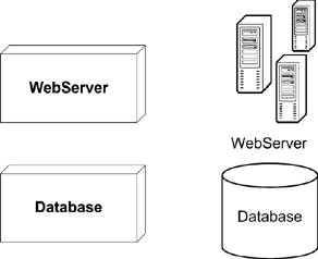 Previous versions of UML did not define any specializations of a node. UML 2.0 specializes a node into two different aspects of hosting code: the required software and the required hardware. Therefore, it is less common to see a generic node in UML 2.0 diagrams than it was in UML 1.x. See "Execution Environments" and "Devices" for more information. 6.2.1. Execution EnvironmentsAn execution environment is a specialized node that represents a software configuration hosting specific types of artifacts. An execution environment is expected to provide specific services to hosted artifacts by means of mutually agreed upon interfaces. For example, a Java 2 Enterprise Edition (J2EE) application expects to run in a software environment called an Application Server. The J2EE specification enumerates several services that should be provided by an Application Server, such as database connectivity, lifecycle contracts, and resource location. You can express that a node is an Application Server (and therefore provides the required services) by defining a stereotype for the node. For example, a typical stereotype for an Application Server is J2EE Container. Figure 6-6 shows an Application Server execution environment. Figure 6-6. A J2EE execution environment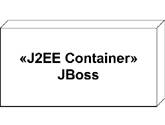 You can specify how services provided by the execution environment are configured using configuration files or deployment specifications (see "Deployment Specifications"). An execution environment is technically a node by itself but is typically shown as part of another, hardware-based node. For example, a J2EE Container may itself be hosted on a machine named AppServer1. You can show the hosting relationship by embedding the execution environment in the hardware node, or by using a composition arrow. Figure 6-7 shows both representations. Figure 6-7. Two representations of an execution environment in a node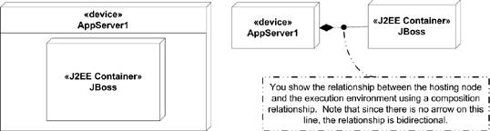 6.2.1.1. Execution environment stereotypesThe UML specification intends for people to create UML 2.0 Profiles that define unique execution environments and their required deployment specifications. These unique environments are each given their own stereotype and are applied to nodes when appropriate. For example, the UML specification suggests stereotypes such as «OS», «database system», and «J2EE Container». 6.2.1.2. Explicit servicesUsually, any services offered by the execution environment are implicit in the stereotype used. However, you may explicitly show the services if that increases the readability of your model. The specification doesn't state how to represent explicit services but suggests listing them in a compartment within the execution environment. Figure 6-8 shows an example execution environment with an explicit list of the services offered. Figure 6-8. An execution environment with explicit services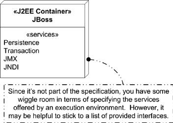 6.2.2. DevicesA device is a specialization of a node that represents a physical machine capable of performing calculations. There are no implied size restrictions on a device; a device can be an embedded controller or the hardware the controller is installed in. You show a device as a node with the stereotype «device». Figure 6-9 shows a node stereotyped as a device. Figure 6-9. A node stereotyped as a device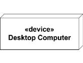 One of the more powerful features of devices is that they can be nested. For example, you can model a server with internal devices representing RAID controllers, video cards, etc. A real-world use of nested devices can be pixel and vertex shading code running on a video card (represented as a device) while the rest of the application runs on the machine's CPU. Figure 6-10 shows an example of what this diagram might look like. Figure 6-10. A device (the video card) nested inside another device (the desktop machine)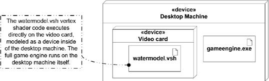 6.2.3. Communication PathsCommunication paths represent generic communication between nodes. For example, a router may pass HTTP requests to a web server that uses a proprietary socket connection to a database. Assuming the database is hosted on its own machine, you can model the deployment of the system as nodes linked via communication paths. The concept of links between nodes existed prior to UML 2.0, however now the specification formally names them. You show a communication path as a solid line drawn from one node to another. You typically don't show any directionality on the line because the communication is assumed to be bidirectional. Figure 6-11 shows an example web server configuration with several nodes communicating over communication paths. Figure 6-11. Several nodes linked with communication paths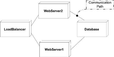 UML doesn't specify a way of modeling the actual messages passed between nodes. However, protocol state machines (see Chapter 8) often provide a good way to represent information flow if a particular protocol is spoken between nodes. If a link represents messages between components that aren't captured in a protocol state machine, it may make sense to link to one or more component diagrams (see Chapter 5) using a note. Figure 6-12 shows an example communication path linked to a component diagram. Figure 6-12. A communication path with a note attached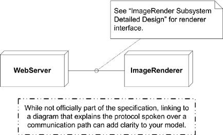 |
EAN: 2147483647
Pages: 132