Section 6.3. Deployment
6.3. DeploymentThe most important aspect of deployment diagrams is conveying the relationship between artifacts and the node(s) they execute on. When you associate an artifact with a deployment target (anything that can host an artifact, such as a device or execution environment), you deploy that artifact. For example, you may have an artifact named ccvalidator.jar that represents the credit card validation subsystem of an application. When you say ccvalidator.jar executes on the node Appserver1, you have deployed the artifact. 6.3.1. Deployment RepresentationUML provides several ways to show deployment. You may show artifact deployment by simply drawing an artifact in the hosting node's cube. Figure 6-13 shows an artifact named ccvalidator.jar deployed to the device Appserver1. UML also allows you to show deployment using a dashed line with an open arrow (dependency) pointing from the artifact to the deployment target. You should stereotype this line with the keyword «deploy». Figure 6-14 shows the same deployment relationship as Figure 6-13, but uses the dependency notation. Finally, you may show deployment by simply listing deployed artifacts in a compartment in the deployment target's classifier. This notation is particularly useful if you have a lot of artifacts deployed to a single node. Figure 6-15 shows an execution environment with several deployed artifacts. Figure 6-13. An artifact deployed to a device Figure 6-14. Artifact deployment using a dependency relationship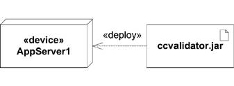 Figure 6-15. An execution environment with a list of the deployed artifacts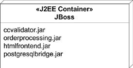 UML 2.0 introduced the term deployed artifact for artifacts that have been associated with nodes. There is no new notation; UML 2.0 just added a formal recognition of the concept. 6.3.2. Deployment SpecificationsA deployment specification is a collection of properties that specify how an artifact is to be deployed on a deployment target. For example, you can specify that an artifact requires database transactions or connection information to communicate with a server. You model the specific deployment information as a deployment specification artifact. You show a deployment specification using the classifier rectangle stereotyped as «deployment spec», with required deployment information as attributes. Figure 6-16 shows an example deployment specification captured in a file named web.xml. Figure 6-16. A sample deployment specification The specific information in a deployment specification depends on the type of artifact being deployed. You may need a separate model to capture the type of information used by the specification. For example, Figure 6-16 uses a type named Resource that should be defined on another diagram. It's common to bundle an artifact and its deployment specification into a larger artifact. You show the relationship between an artifact and its deployment specification using a dashed line with an open arrow (dependency) pointing from the specification to the artifact. Figure 6-17 shows bundling the weatherserver.jar application with its deployment descriptor in a web archive called weatherserver.war. Figure 6-17. An artifact that contains another artifact and its deployment specification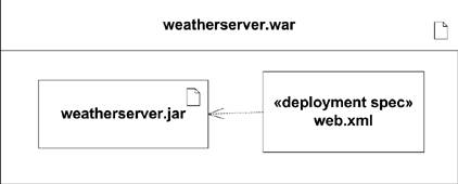 |
EAN: 2147483647
Pages: 132