Controller Location Options
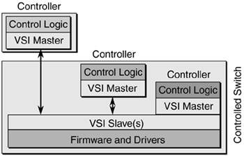
| There are multiple realizations or implementations of the controller/controlled switch architecture. Figure 2-14 summarizes the controller location options. Figure 2-14. Controller Location Options
You can see that three different locations exist for the controller with respect to the controlled switch:
Because the controller can reside on either the switch or off-switch, the choice for lower layers is left for individual implementations. In the first case, where you have a separate controller, there's also a physical interface between the controller and the control switch. That physical interface is not part of the VSI specification, even though there is an appendix in the VSI specification that states how LLC/SNAP/AAL5 encoding over ATM can be used. VSI across Frame Relay, LAN, or a reliable message transport such as TCP or SSCOP is not currently defined, but it might be defined in future versions of the VSI specification. When using ATM, the controller and switch use ATM VCs to communicate with each other. As shown in Equation 2-1, there is one ATM PVC per slave using these virtual path identifiers (VPIs) and virtual circuit identifiers (VCIs) by default: Equation 2-1 Default VPIs/VCIs Used by VSI
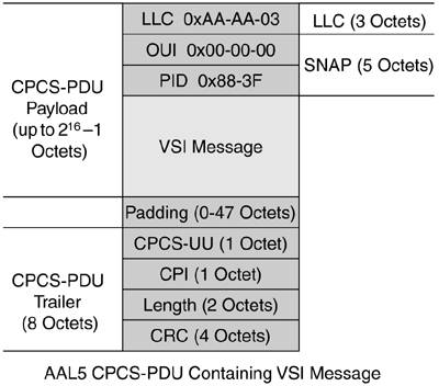
These are the default VPI and VCI values used. They can be changed in some implementations by mutual agreement between the master and the slaves (in other implementations, they are fixed). In the case of a centralized VSI slave, the slave-id is 0, so the VCI is 40. The encapsulation used is AAL5 LLC/SNAP, as shown in Figure 2-15. Figure 2-15. ATM Encapsulation of VSI Messages
The VSI message is directly encapsulated in AAL5 using Common Part Convergence Sublayer Protocol Data Unit (CPCS-PDU), LLC/SNAP header. The presence of a SNAP header is indicated by the LLC header value of 0xAA-AA-03. A SNAP header has two fields: OUI (Organizationally Unique Identifier) and PID (Protocol Identifier). An OUI value of 0x00-00-00 states that the following PID is an Ethertype. A PID of 0x883F indicates that the PDU is a VSI message. NOTE The LLC/SNAP header described in Figure 2-15 corresponds to the VSI specification that was submitted to the Multiservice Switching Forum. As a Cisco Systems extension to VSI, the implementation of VSI over AAL5 LLC/SNAP uses a proprietary header value: a Cisco OUI of 0x00000C with a PID of 0x0103, indicating VSI. |
EAN: 2147483647
Pages: 149