Hard, Soft, and Dynamic Resource Partitioning
| Even though resource partitioning is not required for VSI, it's of paramount importance to support multiservice switching networks. The Resource Management Module (RMM) in the VSI slaves is the enabler of the multiservice functionality. As you know, interfaces have resources associated with them (such as VPI/VCI ranges, bandwidth, and number of channels). A multiservice switch supporting multiple controllers must assign some resources to each controller (at least, it must assign interfaces to different controllers). Some of those resources must be used exclusively by one controller, such as VPI/VCI ranges, and others can be exclusive or shared with other controllers, such as bandwidth. A partition is an allocation of resources for use by a specific controller, such as MPLS or PNNI. After assigning resources to different partitions on the same interface, the switch must then advertise only the resources allotted to a given partition to the controller assigned to the partition. This defines the creation of the virtual switch, and the controller does not need to know that the interface has resources partitioned. The resources might also include pooled resources. In Figure 2-16, resources are partitioned in the interface and are assigned to two controllersPNNI and MPLS. The resources are channel or logical connection number (LCN) space, bandwidth, and VPI/VCI space. Figure 2-16. Resource Partitioning
A mechanism must exist to share those resources among various partitions assigned to different controllers. There are two ways to do that: hard partitioning and soft partitioning. A few key points to remember when it comes to assigning resources to a partition during configuration are
Hard PartitioningVPI/VCI space partitioning is strict, meaning that one VPI/VCI range is assigned to one and only one owner controller, and it cannot be shared with other controllers. VPI/VCI ranges do not overlap among partitions. The term to describe these kinds of partitions is hard partitioning. In a hard partitioning method, each controller gets a fixed amount of resources (bandwidth or channels). Although this is a straightforward scheme, the drawback is that the resources can be used inefficiently. NOTE In the case of AutoRoute-to-PNNI migration, soft partitioning of VPI/VCI resources is implemented with some restrictions. In other words, different control planes can have an overlapping VPI/VCI space. Soft PartitioningIn contrast to hard partitioning, soft partitioning of resources has two implications:
One way of complying with both requirements of soft partitioning is to specify a minimum and maximum amount for each resource when soft partitioning those resources. The minimum is the guaranteed value, and the maximum is the upper boundary provided that the extra resources are available and are not used by other partitions. In other words, this allows for a common pool of shared resources. Bandwidth Soft PartitioningThis list defines bandwidth soft-partitioning concepts:
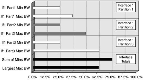
Users only directly configure the minimum and maximum partition bandwidth. The rest of the values are calculated from these two. To make this point completely clear, let's analyze two examples of bandwidth partitioning between three partitions in the same interface. See Figures 2-17 and 2-18. Figure 2-17. Soft Partitioning of Bandwidth Resources
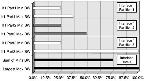
Figure 2-18. Soft Partitioning, Part 2
For each partition in each interface, you define the Partition_Minimum_BW and Partition_Maximum_BW. The first requirement is to guarantee the minimum bandwidth for all the partitions in the interface. The bottom sections in Figures 2-17 and 2-18 specify the sum of the minimum bandwidth for all bandwidth partitions on the interface. So the bandwidth reservation for the entire interface must be at least equal to that sum, which is 75 percent of the bandwidth in the interface. As shown in Figure 2-17, reserving Interface_VSI_reserved_BW equal to the sum of the minimums (75 percent) is enough to guarantee the minimum bandwidth for each resource partition in the interface. In this case, when the bandwidth reserved for VSI for the interface equals the sum of the minimums, there is no pool of shared bandwidth (Interface_VSI_PoolSize_BW = 0), so no partition can reach its maximum bandwidth. The important concept is that only the minimum must be guaranteed. As shown in Figure 2-18, if partitions 1 and 2 are transmitting at their minimum bandwidths, but the reservation of bandwidth for the interface is 100 percent, partition 3 can go beyond its minimum. In this case, Interface_VSI_reserved_BW needs to be set to the largest maximum bandwidth value. Note that partition 3 can never achieve its maximum bandwidth of 100 percent, because the minimum bandwidth allotted to partitions 1 and 2 must be maintained. The cases shown in Figure 2-18 can be summarized using the formula shown in Equation 2-2: Equation 2-2 Per Interface VSI Reserved Bandwidth
The bandwidth reserved for VSI in the interface (Interface_VSI_reserved_BW) is equal to the sum of all the minimum bandwidths, or the largest of all the maximum bandwidths of all the partitions in the interface, whichever is greater. If the bandwidth is soft-partitioned, the difference between the largest maximum bandwidth value and the sum of all the minimum bandwidths of all the partitions is a common resource to be used by any partition that needs it, provided that the partition does not exceed its own maximum bandwidth. This is what we defined earlier as Interface_VSI_PoolSize. In the case shown on the right side of Figure 2-17, 25 percent of the interface bandwidth is shared between the three partitions. If partitions 1 and 3 are transmitting at their minimum bandwidths, partition 2 can reach its maximum bandwidth of 50 percent. On the other hand, if partitions 2 and 3 are transmitting at their minimum bandwidths, partition 1 can transmit at its maximum of 37.5 percent, and 12.5 percent of the interface bandwidth is left for partitions 2 and 3 to share. Consider the formula in Equation 2-3: Equation 2-3 Per Interface VSI Bandwidth Poolsize
You subtract the sum of the minimum bandwidths from the largest maximum bandwidth value. If the difference is greater than 0, an interface bandwidth pool (Interface_VSI_PoolSize_BW) exists. Otherwise, there is no interface bandwidth pool. To determine a particular partition's pool size (Partition_VSI_PoolSize_BW), you compare the interface pool size to the difference between the maximum and minimum bandwidths for that partition, and then you assign it the smaller value. For the ith partition, you have Equation 2-4: Equation 2-4 Per Partition VSI Bandwidth Poolsize
This means that the partition does not use more than its configured maximum value if there is shared bandwidth. LCN or Channel Soft PartitioningFrom a different viewpoint, resources can belong to the interface, to a set of interfaces, or to the entire card. VPI/VCI space and bandwidth clearly belong to the interface. In the case of bandwidth, we just pointed out how the resource pool applies at the interface level. But in some cases, the LCN (the number of connections) might be a resource belonging to a set of interfaces called a port group. To refresh the definition, a port group is a set of interfaces that share LCN resources and that might contain multiple interfaces. The concept of soft partitioning has significance only in the interfaces that can actually share resources among them. When bandwidth is soft-partitioned, it's meaningful only within the interface. Likewise, when LCN is soft-partitioned, it is significant in the port group. The corresponding LCN or channel soft-partitioning concepts are defined in the following list:
The user configures the Partition_Minimum_LCN and Partition_Maximum_LCN values. The rest of the values are derived from these two. The same rules as with bandwidth resources apply to LCN resources, taking into account that LCN resources generally span multiple interfaces because of chip implementations. For LCN resources, the reservation is done at the port group level, including different interfaces. Given the following partition information, let's see how to calculate the partition and port group LCN pool sizes, the port group reserved LCNs, and the partition-available LCNs. Table 2-2 shows the configured minimum LCN and maximum LCN values for each partition in every interface and in each port group.
Using the formulas for port group, you first calculate the port group VSI reserved LCN and port group VSI pool size LCN. For LCN resources as well, the number of LCNs reserved for use by VSI in the port group is the greater value of the sum of the minimum LCN values and the largest maximum LCN value for every resource partition in the port group. See Equation 2-5: Equation 2-5 Per Portgroup VSI Reserved LCNs
The LCN pool size is the difference between the largest maximum LCN value and the sum of the minimum LCN values if it is greater than or equal to 0. It is 0 otherwise. See Equation 2-6: Equation 2-6 Per Portgroup VSI LCN Poolsize
Table 2-3 shows the reserved LCN and LCN pool size per port group from comparing the sum of the minimum LCN to the largest maximum LCN.
For the first and second port groups, the largest maximum LCN is greater than the sum of the minimum LCNs, meaning that there will be a pool size. The third port group has a null shared pool of LCN resources, because sum(Mins) is greater than max(Maxs). Finally, you can calculate the partition LCN pool size and available channels for each partition using the following two formulas. This first formula shows that you determine the LCN pool size for a given partition by comparing the port group pool size to the difference between the maximum and minimum LCN values for a given partition and choosing the smaller. This formula ensures that you do not use more than the maximum LCN allotment. See Equation 2-7: Equation 2-7 Per Partition VSI LCN Poolsize
Now that you know the partition pool size, you can easily determine the partition's available LCNs using the formula in Equation 2-8: Equation 2-8 Available LCNs
Table 2-4 provides the final objective of this exercise. It shows the pool size and available LCNs on a per-partition basis.
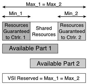
For partition 1 in interface 1 and port group 1, the difference between the maximum LCN and minimum LCN (from Table 2-3) is less than the port group pool size (from Table 2-4). This means that the partition can reach its maximum, provided that LCN resources are available. For the rest of the partitions in the same port group, the port group LCN pool size (from Table 2-4) is the lower value, so those partitions can't reach their configured maximum LCN value. If LCN resources are available (channels not used), the partitions can use only 1500 LCNs and 2000 LCNs, respectively. This ensures that the minimum LCN is guaranteed for the other partition in the port group. Finally, partitions in port group 3 have a null partition pool size, meaning that at most they can use their minimum configured LCN. More Soft-Partitioning ExamplesThis section discusses two examples of VSI resource partitioning. It introduces a graphical approach to resource partitioning. The first example describes a scenario with equal maximum partition sizes, and the second example presents a case with different maximum partition sizes. The two examples strengthen the concepts of resource partitioning with figures that demonstrate how the partitioning interrelationships work. The figures also help you understand the virtual switch concept covered later in this chapter. Example 1: Equal Maximum Partition SizesFigure 2-19 represents the soft partitioning of resources for use by two VSI controllers. These resources can be bandwidth in an interface or LCNs in a port group. Remember that, in soft partitioning, you specify a minimum and a maximum for each partition. In this particular case, the maximum for both partitions is the same. Figure 2-19. VSI Resource Partitioning Where Max_1 = Max_2
The first concept to mention is that the guaranteed resources in each partition are equal to the minimum configured for the partition. Because both Max_1 and Max_2 are larger than the sum of the minimums (Min_1 + Min_2), you set VSI Reserved equal to the larger of Max_1 and Max_2. See Equation 2-9: Equation 2-9 Soft Partition Example 1
The difference between VSI Reserved (in this example, equal to Max_1 and Max_2) and the sum of the minimums (Min_1 + Min_2) represents a pool of shared resources. These two definitions (VSI reserved and shared resources) are meaningful within the scope of the specific type of resources. If the resources being partitioned are bandwidth resources, the scope is the physical interface. If the resources being partitioned are LCN resources, the VSI reserved and shared resources apply at the port group level. In both partitions, the difference between the maximum and the minimum is larger than the shared resources, so either partition can fully utilize the shared resource pool. Consequently, the corresponding available resources for each partition are the sum of the guaranteed resources (the minimum resources) plus the shared resources. The partition pool size for both partitions equals the VSI pool size of shared resources. Example 2: Different Maximum Partition SizesOn the contrary, if the maximums of both partitions are not the same, you can use the case shown in Figure 2-20. Figure 2-20. VSI Resource Partitioning Where Max_1 <> Max_2
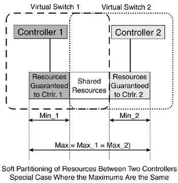
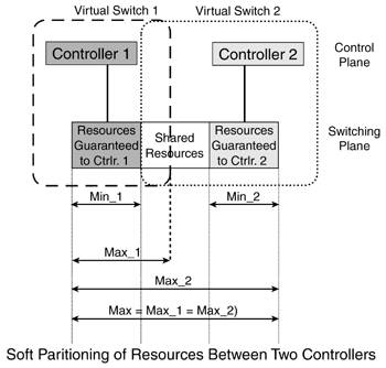
In this case, the VSI reserved resources are still based on the maximum of the maximums. However, Max_1 is smaller than Max_2. Although the shared resources are the same as before, some differences in the partition behavior exist. The available resources for partition 2 are the same as before and are equal to the minimum resources plus the shared resources. On the other hand, for partition 1, the difference between Max_1 and Min_1 is smaller than the shared resources, so the available resources for partition 1 are equal to the maximum for the partition, because it cannot use beyond its configured maximum. The partition pool size for partition 1 is Max_1 minus Min_1. Soft Partitioning and Virtual SwitchesIt is interesting to see the virtual switches that are "created" by partitioning the controlled switch. For the special case in which the maximums are equal to or larger than the sum of the minimums, Figure 2-21 shows different guaranteed and shared resources. Figure 2-21. Virtual Switch Representations for the Case Where Max_1 = Max_2
Conversely, if the partition pool size for one partition is smaller than the shared resources, we have the scenario shown in Figure 2-22. Figure 2-22. Virtual Switch Representations for Restricted Partition Pool Size
Note that virtual switch 1 is now "smaller," meaning that it has fewer resources available. As a consequence, virtual switch 2 has more resources of its own that it does not share with virtual switch 1. Finally, if the VSI reserved comes from the sum of the minimums (when the sum of the minimums is greater than or equal to the largest of the maximums), there are no shared resources, as shown in Figure 2-23. Figure 2-23. Virtual Switch Representations Where sum(Mins) |


 max(Maxs)
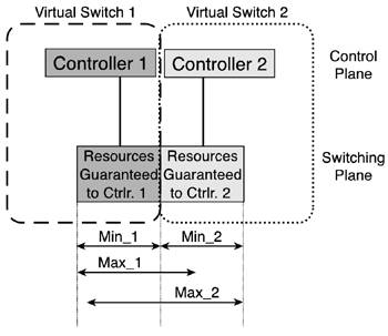
Min LCN | Max LCN | |
|---|---|---|
Interface 1 | 1000 | 4000 |
Interface 2 | 1000 | 4000 |
Interface 3 | 1000 | 4000 |
The port group to which all four interfaces belong has 4000 LCNs reserved for VSI.
The port group pool has 1000 LCNs, as well as the partition pool for each partition; therefore, each partition has 2000 LCNs available.
Suppose that, currently, interfaces 1 and 2 are using 1000 LCNs and interface 3 is using 2000 LCNs, using up all the resources available. At this point, you add a new resource partition in interface 4 with 1000 guaranteed LCNs. This new partition is shown in Table 2-6.
Minimum LCN | Maximum LCN | |
|---|---|---|
Interface 1 | 1000 | 4000 |
Interface 2 | 1000 | 4000 |
Interface 3 | 1000 | 4000 |
Interface 4 | 1000 | 4000 |
Figure 2-24 shows the use of LCN resources in the existing partitions as well as in the new partition.
Figure 2-24. Starved Partition
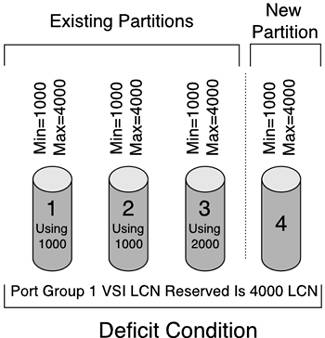
Figure 2-24 shows that this new partition does not have enough LCNs to satisfy the minimum, because the third interface's partition is using all the LCNs from the previous pool of 1000 LCNs. This newly added partition is marked as starved, meaning that not enough free LCN resources are present to satisfy this partition's minimum requirement. Those LCN resources are used by the existing partitions because they belong to a common pool. For the purposes of not disrupting service, it's desirable that those LCNs are not taken away from interface 3, but when interface 3 frees one LCN, that LCN is automatically assigned to interface 4. When the deficit state is over, there's no way of reaching the same condition again, because now the port group pool size is 0 LCNs, so each partition's pool size is 0 LCNs as well.
Dynamic Partitioning
Although the term dynamic partitioning is used in industry literature, it is actually a misnomer; it should be called dynamic repartitioning. It applies to hard or soft partitioning and allows the operator to increase or decrease a partition's resource allocation with minimal impact to service. Without dynamic partitioning, a user would have to delete the resource partition and re-add it with the new values.
The partitioning function resides in the VSI slave modules. Therefore, the implementation of the dynamic partitioning capability is both platform-dependent and release-dependent.
EAN: 2147483647
Pages: 149