End-to-End Connections
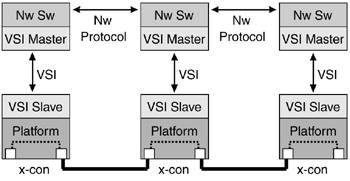
| This section analyzes the steps involved in the creation of an end-to-end connection. As you know, the multiservice switching architecture is based on the separation of the switching plane and the control plane. A general three-node network might look like Figure 2-11. Figure 2-11. Multiservice Switching Network: End-to-End Connections
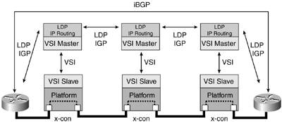
Based on the networking protocol running in the controllers (at the networking protocol layer), the VSI master instructs the controlled switch to set up the cross-connects that are the segments of the end-to-end connections. The controlled switch does not know the end-to-end connection information or topology, only the local cross-connect. If the controllers are MPLS controllers, the networking protocol is LDP and an IGP, such as OSPF or IS-IS. The label distribution mechanism is Downstream on Demand, and will be discussed in detail in chapters 4 "Introduction to Multiprotocol Label Switching" and 6 "MPLS Implementation and Configuration." Figure 2-12 shows a multiservice switching MPLS network. Figure 2-12. Multiservice Switching Network: MPLS Example
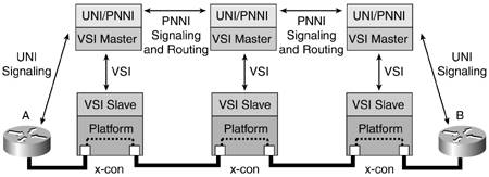
NOTE The label distribution technique used in ATM LSR has some variations that are detailed in Chapters 4 and 6. For ATM-LSRs that are not VC-merge-capable, the distribution mechanism must be Downstream on Demand, and optionally is the same for ATM LSRs that support VC-merge. Downstream on Demand has two control modes: independent (optimistic label allocation) and ordered (conservative label allocation). These are defined in RFC 3031 ("Multiprotocol Label Switching Architecture") and RFC 3036 ("LDP Specification"). These variations determine how end-to-end connections are signaled and set up, and thus at which point the cross-connects are installed in the controlled switches. NOTE Here is the definition of VC-merge in RFC 3035 ("MPLS Using LDP and ATM VC Switching"), Section 3: "VC-merge is the process by which a switch receives cells on several incoming VCIs and transmits them on a single outgoing VCI without causing the cells of different AAL5 PDUs to become interleaved." NOTE A VPN MPLS network also has edge-to-edge communication. The PE (Provider Edge) devices have an iBGP neighboring relationship. Let's explore a complete example of how a controller can set up and tear down a connection segment of an end-to-end connection in a multiservice switching PNNI network. See Figure 2-13. Figure 2-13. Multiservice Switching Network: PNNI Example
The first part of the example details the steps that occur in a Connection SETUP:
The preceding is a simplified example from a Q.2931 point of view, trying to emphasize VSI messaging in every step. The details of PNNI signaling will be covered in Chapters 8 "PNNI Explained" and 10 "PNNI Implementation and Provision." The second part of the example describes the stages in a Connection RELEASE process:
|
EAN: 2147483647
Pages: 149