| As stated in Chapter 10, MPLS traffic engineering (MPLS-TE) addresses the following issues (also see Figure B-3): Link congestion Interior gateway protocol (IGP) best paths might be overused while alternative paths are either underutilized or not used at all. For example, in Figure B-3, the link between C and D is never used to forward traffic from A to F. All the packets go through B, which is the path with fewer hops. You can make the IGP use a different path by including bandwidth as one of the link metrics for shortest path first (SPF) calculation, but this is an approximate science and one that has no notion of congestion. Link protection If a path or device failure occurs along the primary link switched path (LSP) in Figure B-3, routing protocols have to rerun the full SPF calculation before traffic can be forwarded again, which can take several seconds. Load balancing Standard IGPs allow traffic to be balanced equally across equal-cost paths only. Unequal paths are ignored because the IGP sees them as longer routes to the destination, which is why the C-to-D link in Figure B-3 is not used in the first place.
Figure B-3. Fish Problem 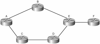
MPLS-TE calculates shortest paths through a network, but within a given set of constraints using constraint-based routing (CBR). The operation is as follows (with the final result shown in Figure B-4): All routers in the network run a link-state routing protocol with an extension that uses reservable link bandwidth as a metric. The tunnel headend, Router A in Figure B-4, determines the best path to Router F based on available bandwidth, using a variant of standard SPF called constrained SPF (CSPF). CSPF prunes candidate paths from the SPF tree that do not satisfy some constraint (in this case, available bandwidth). In Figure B-4, the tunnel needs 40 Mbps. Router A finds the path to be A to C to D to E to F (perhaps because of slow or congested links elsewhere). The path appears as a dotted line in Figure B-4. As link-utilization conditions change, the CSPF algorithm will give different results for the same destination, which is the intended result. After the path is found, the headend reserves a path through the network. Reservation is done using the Resource Reservation Protocol (RSVP) to signal label values. The headend sends a PATH message to the far end of the tunnel. The RSVP message follows the intended path of the tunnel, as defined by the CBR calculation. Each LSR along the path checks whether it can allocate the requested bandwidth to the tunnel and updates the RSVP payload accordingly. The remote endpoint sends an RSVP RESV message back along the tunnel path. When it receives the RESV message, each LSR along the path reserves the bandwidth and allocates a label for the tunnel. The label data is communicated to the upstream LSR in the RSVP message. In more informal terms, the PATH message asks routers "please reserve this amount of bandwidth to this destination?" The RESV reply says "yes, I did so and here is the label to use to access the bandwidth I just set aside." Remember, though, that RSVP is a control plane reservation mechanism. Standard interface QoS mechanisms are required to implement policy. After they are built, the tunnels, which appear as an IOS interface, still need to be included in the routing tables before a router can use them. You can do this with simple static routes on the headend router or by announcing it through the IGP as a directly connected path. Policy routing is a third option. The tunnel is ready for use, with the label values defined at each hop along the LSP.
Figure B-4. 40-Mbps TE Tunnel Established 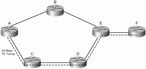
|