Hierarchical Campus Design
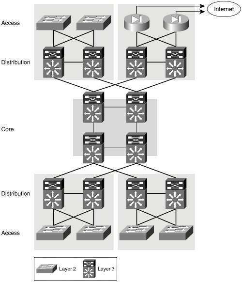
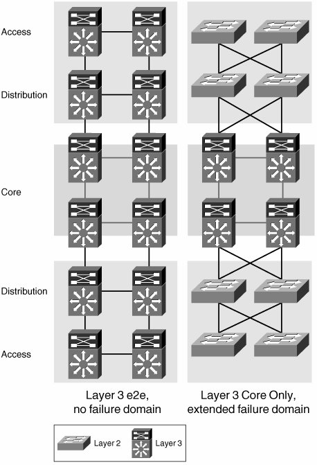
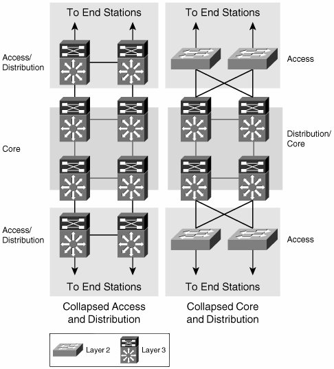
| The recommended approach to designing campus networks is one that is both hierarchical and modular. This hybrid approach makes the campus network highly resilient, scalable, and easy to maintain. As shown in Figure 2-1, traffic is aggregated hierarchically from an access layer into a layer of distribution switches and finally onto the network core. At each layer of this hierarchical topology, redundant components connect in a redundant topology. This redundancy of links and components provides the campus network with resilient and symmetric traffic paths. These symmetric traffic paths provide network-level resiliency and optimize the convergence of networking protocols. For instance, routing protocols will benefit from symmetric paths by having multiple equal-cost paths to a destination, which allow for virtually immediate failover. Figure 2-1. Hierarchical/Modular Campus Network Modularity is achieved by pairing distribution switches to aggregate a group of access switches and thus provide resilient access to the core for entire physical network areas. These network areas can include an entire building or several floors in a large building. A distribution module can also be used to connect WAN aggregation routers, Internet access routers, or a data center to the campus core. You can add or remove distribution modules to or from the network with minimal or no impact to other modules. As these modules are added, symmetric paths to all other modules are automatically created. However, a greater benefit of a modular and hierarchical architecture is that failures are intrinsically isolated. This isolation occurs at many levels, the first of which is the isolation of broadcasts by the termination of all access VLANs onto a routed distribution. The presence of a routed distribution and core minimizes the size of the Layer 2 broadcast domains and isolates them from the rest of the network by preventing the spread of broadcasts beyond the domain. Within the Layer 3 core and distribution layers, the use of a hierarchy, by means of summarization and area creation, prevents a change in one portion of the network from causing the reconvergence of the entire routed domain. Let's discuss these isolation mechanisms in more detail. The different layers of the campus network must fulfill certain roles, which require specific features and functionality. For instance, a distribution switch simultaneously has the roles of a Spanning Tree Protocol (STP) root bridge, a first-hop router, and a quality of service (QoS) policing enforcement point. In contrast, an access switch does not require routing or even that it be an STP root candidate. However, it does require many features related to the connectivity of hosts into the network such as in-line power, QoS trust functionality, authentication mechanisms, and so on. A key component of enterprise network scalability is the use of Layer 3 (routed) technologies at the core and distribution layers of the network, while using Layer 2 (switched) connectivity to aggregate the access switches into the distribution layer, as shown in Figure 2-1. This model is the most common practice today because it minimizes the size of Layer 2 failure domains while keeping the deployment of routing protocols simple. A failure in a Layer 2 domain usually propagates over the entire Layer 2 domain; this model restricts the propagation of failures by terminating the Layer 2 domain at the distribution layer. Some examples of failures that can cause broadcast storms include STP loops and jabbering network interface cards (NICs). In this topology, a failure might affect an entire module but should not be able to propagate into the core. Preventing the propagation of failures depends not only on the hierarchical nature of the network topology and the termination of Layer 2 domains, but it also depends on the hierarchical deployment of the networking protocols used. Therefore, an interior gateway protocol (IGP) deployment that uses a hierarchical routing structure to present the core with a summary of the prefixes present in every distribution module will be less likely to face a global reconvergence than a deployment without any hierarchical routing considerations. It is important to emphasize that the hierarchy and symmetry of the physical topology actually allows the campus architect to fully exploit the benefits of the network protocols, not only by creating a hierarchy capable of containing the effect of network changes, but also by creating symmetrical paths that allow the networking protocols to leverage equal-cost paths in their calculations. The use of equal-cost paths enables extremely fast failover times, which do not depend on protocol reconvergence. This is a classic example of how a well-designed topology allows for the best use of the networking protocols and how a good use of the networking protocols exploits the benefits of a resilient and hierarchical topology. As shown in Figure 2-2, deploying Layer 3 switching all the way to the access layer also represents a viable solution. However, this design choice could create added challenges when attempting to virtualize the network transport. These challenges will become evident as we analyze the different virtualization technologies for the campus in Chapter 6, "Infrastructure Segmentation Architectures: Practice." Figure 2-2. Extension of Failure Domains Alternatively, the extension of Layer 2 VLANs throughout the access and distribution layers could be considered. This might be attractive to network architects seeking the virtualization of the network transport, because VLANs actually achieve such virtualization at Layer 2. However, the extension of switched domains requires extreme caution in its implementation because strict failure-isolation mechanisms must be put in place to protect the core from a now-extended failure domain. Furthermore, by reducing the size of the Layer 3 domain in the core, you lose many of the benefits of a Layer 3 area. Some of the lost functionality includes load balancing or even traffic engineering over symmetric paths and most of the fault isolation a hierarchical Layer 3 core/distribution can provide, not to mention the added complexity of maintaining larger Layer 2 domains and the required spanning tree. In general, the extension of failure domains is not recommended. Similarly, as the extension of Layer 2 and Layer 3 domains can vary for different networks, so can the roles of access and distribution or core and distribution. For example, they can be collapsed together onto a single layer of switches. In a network where the distribution and access are collapsed, the distribution switches also act as access switches (as shown in Figure 2-3). Collapsing network layers in this manner limits the port densities that can be handled by the network and thus its scalability. Therefore, this solution is normally chosen for networks of limited size that expect little growth. Figure 2-3. Collapsed Network Roles In the specific example where the distribution and core are collapsed, the core is directly exposed to failures in the access. This type of design calls for specific failure-isolation features to improve the required level of availability in the network. Even though they offer an improvement, features such as storm suppression and sophisticated spanning tree cannot deliver the same level of resiliency achieved by a hierarchical architecture leveraging a multilayer routed core. The limitations of this reduced Layer 3 core are the same as those already discussed for an extended failure domain: loss of load balancing, limited scalability, and lack of fault containment. |
EAN: 2147483647
Pages: 128
- Chapter V Consumer Complaint Behavior in the Online Environment
- Chapter VII Objective and Perceived Complexity and Their Impacts on Internet Communication
- Chapter VIII Personalization Systems and Their Deployment as Web Site Interface Design Decisions
- Chapter XV Customer Trust in Online Commerce
- Chapter XVII Internet Markets and E-Loyalty