8.3 Protocol Architecture
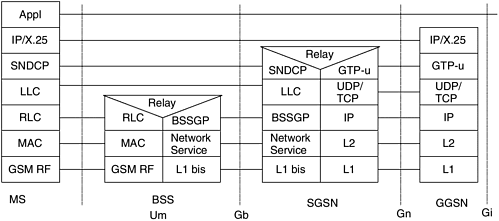
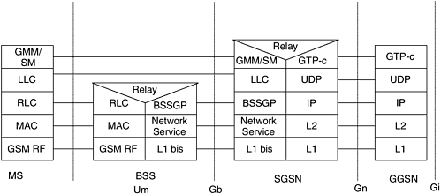
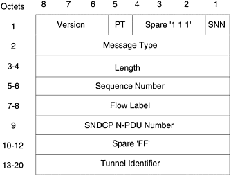
| All the NEs of the GPRS network interact with each other using separate user and control plane protocol stacks. The protocol stacks of the SGSN/GGSN with HLR and EIR are the same as the MSC/VLR with HLR and EIR (i.e., MAP/TCAP over SCCP/MTP). Hence, we do not describe them in this chapter. The protocol stacks among GGSN, SGSN, BSS, and MS are new and are described in this section. 8.3.1 User PlaneThe data packets are tunneled between the GGSN and SGSN using the GPRS Tunneling Protocol (GTP) (Figure 8-3). The GTP packets can be carried either in acknowledged (TCP) or unacknowledged mode (UDP) over IP. The SGSN uses the SNDCP (Subnetwork Dependent Data Convergence Protocol) to adapt the network PDUs so they can be transmitted through the radio network. For this purpose, the SNDCP performs functions like compression and segmentation. The segmented and compressed packets are processed by the logical link control (LLC) layer. LLC provides a reliable ciphered logical link from the SGSN to the MS. The user data are transmitted between the SGSN and BSS by using BSS GPRS Protocol (BSSGP). The BSSGP PDUs are transported using a frame relay-based connection called network services (NS). Readers can refer to GSM TS 08.16 for details on NS. Radio link control (RLC) is used over the air interface to provide segmentation and assembly of radio blocks into LLC frames . It also provides a radio-dependent reliable link. Underneath the RLC is the media access control (MAC) layer, which provides the mapping to the physical channels. Figure 8-3. User plane protocol stack. Source: ETSI 2002. Further use, modification, and redistribution is strictly prohibited . ETSI standards are available from http://pda.etsi.org/pda/ and http://www.ets.org/eds/. 8.3.2 Signaling PlaneThe signaling plane consists of protocols for control and support of the user plane functions (Figure 8-4). The GGSN and SGSN exchange control information for managing GTP using GTP-c, which is carried over UDP/IP. For establishing and managing a packet data session, the SGSN and MS use the Session Management (SM) protocol. For managing mobility of an MS, the SGSN and MS use the GPRS Mobility Management (GMM) protocol. The GMM has defined procedures for registering and authenticating an MS in a visiting GPRS network. The LLC provides a reliable ciphered logical link over the radio interface for the signaling plane. The SGSN and BSS use BSSGP for managing the signaling connection between them. The BSSGP is used to convey routing and quality of service (QoS) information between the BSS and SGSN. The RLC is used over the air interface to provide a GSM radio-dependent reliable link. The MAC layer controls the access signaling (request and grant) procedures for the radio channels and provides mapping to the physical channels. Figure 8-4. Signaling plane. Source: ETSI 2002. Further use, modification, and redistribution is strictly prohibited. ETSI standards are available from http://pda.etsi.org/pda/ and http://www.ets.org/eds/. 8.3.3 GPRS Tunneling ProtocolGTP is used for both signaling (GTP-c) and data transfer (GTP-u) procedures between the GSNs. It provides a header, which together with the UDP/TCP and IP header identifies the destination GSN and handling of the packet at the destination. There is another variant of GTP, called GTP', which is used as a charging protocol. GTP' is used between GSNs and CGF. In the signaling plane, GTP-c is a tunnel control and management protocol that is used to create, modify, and delete the tunnels between the GSNs. These signaling procedures are called Packet Data Protocol (PDP) Context Request, PDP Context Update, and PDP Context Delete. These procedures are invoked as a part of session establishment or mobility management between the SGSN and the MS. In the user plane, GTP-u provides a GTP header for the user plane tunneling. In addition to the tunneling, GTP-u provides features like in-sequence delivery and multiplexing of flows. The GTP header is a fixed-format 20-byte header, as shown in Figure 8-5. The same GTP header is used for both GTP-c and GTP-u. A GTP-c PDU is distinguished from a GTP-u PDU by a unique message type. Figure 8-5. GTP header fields. The GTP header contains the following fields:
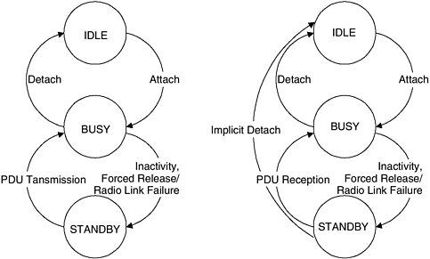
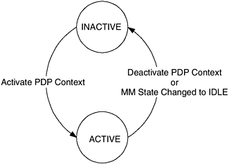
8.3.4 GPRS Mobility ManagementMobility is managed by maintaining different MM states in MS and SGSN (Figure 8-6). There are three MM states: IDLE, BUSY, and STANDBY. In the IDLE state, no MS location information is kept in the network. In the BUSY state, the GPRS MS is known to the network at a cell level. In the STANDBY state, the MS is known to the network at a routing area identifier (RAI) level. The RAI is a location identifier and denotes an area represented by a group of cells . The STANDBY state helps in reducing the battery consumption of an MS. This is because the RAI, being larger then the cell size, changes less frequently for an MS. The STANDBY state is reached from the READY state, when there is no activity for an MS for a certain time. The mobility procedures are executed based on the MM states. Some of the important mobility procedures are explained next . Figure 8-6. MM state diagram in MS and SGSN. Source: ETSI 2002. Further use, modification, and redistribution is strictly prohibited. ETSI standards are available from http://pda.etsi.org/pda/ and http://www.ets.org/eds/. GPRS ATTACH AND DETACH PROCEDURESThe GPRS attach procedure registers an MS with an SGSN for the GPRS services. It informs the HLR, which SGSN can access the MS. When the MS sends an attach request, the network checks if the user is authorized and copies the user profile from the HLR to the SGSN. The GPRS detach procedure performs the reverse operation; it disconnects an MS from the GPRS services. LOCATION MANAGEMENTThe network keeps track of the user's current location in terms of a cell or routing area (RA) by executing the cell update or RA update procedures, respectively. A routing area is a geographical location kept by the network to track MS in idle mode. It provides the serving cell information in the system information messages. The MS detects that a new cell has been entered, by comparing the cell's identity with the cell identity stored in the MS's MM context. Similarly, the MS detects that a new RA has been entered by periodically comparing the RAI stored in its MM context with that received from the new cell. The MS performs the cell update procedure when it enters a new cell inside the current RA and it is in the READY state. The MS sends an uplink LLC frame of any type containing the MS's identity to the SGSN. The BSS, as part of BSSGP, adds the cell global identity to the LLC PDU and sends it as a BSSGP PDU toward the SGSN. The SGSN records this change of cell and directs further traffic toward the MS over the new cell. A GPRS attached MS initiates RA update when it detects that it has entered a new RA. The SGSN performs intra-SGSN RA update if the old RA is also being served by the same SGSN. In this case, there is no need to inform the GGSNs or the HLR. When the SGSN detects that it doesn't handle the old RA, it performs an inter-SGSN RA update. In this case, the new SGSN interacts with the old SGSN to get the context information. It also updates the GGSN or the HLR about the new MS location. The RA update can also be triggered as a result of periodic RA update procedure, which ensures that regular radio contact is maintained by the mobile. The periodicity of this RA update is determined by the network. SECURITY FUNCTIONSOne of the important requirements for packet access is security. GPRS builds its security procedure on the already proven GSM security procedures. There are three main security functions provided by GPRS: user authentication, user identity confidentiality, and data/signaling ciphering. The user authentication function is provided to guard against unauthorized GPRS service usage. This is done by performing user authentication and user service request validation procedures. The user identity confidentiality is provided over the air interface by allocating a temporary identity. The ciphering function is for data and signaling encryption over the air interface. The GPRS authentication procedure is very similar to the GSM authentication procedure. At the time of GPRS attach, the authentication triplets (a random number, signed response, and a key) are stored in the SGSN. The triplets are used in verifying the user access and setting up of the ciphering. The SGSN also uses a temporary identifier, called P-TMSI signature, for identifying a user. The P-TMSI signature is sent by the SGSN to the MS in attach accept and routing area update accept messages. The MS includes the P-TMSI signature in the next routing area update request and attach request for its identification. If the P-TMSI signature does not match, the SGSN initiates the user authentication functions. The GPRS network also supports the IMEI check procedure for lost and stolen mobile equipments. The IMEI check procedure is the same as in GSM and uses a centrally located equipment identification register (EIR) in the home PLMN. For the user identity confidentiality, the temporary logical link identity (TLLI) is used for identifying a GPRS user. The relationship between TLLI and IMSI is known only in the MS and SGSN. The TLLI is derived from the P-TMSI, which is usually allocated by the SGSN. The P-TMSI is allocated as part of the attach or RA update procedure. The P-TMSI can also be reallocated by using the P-TMSI reallocation procedure at any time when the MS is in the READY state. GPRS ciphering is similar to GSM ciphering. It has two main differences from GSM ciphering. First, GPRS ciphering is between the MS and the SGSN as compared to being between the MS and BSS in GSM. Second, GPRS ciphering uses LLC frame numbers in the algorithm as compared to the TDMA frame number in GSM. This is because the TDMA frame number, a radio parameter, is not available in the SGSN. 8.3.5 Session ManagementAn MS needs to establish a session with the GPRS network before it can exchange packets with the external packet data network. A GPRS user is subscribed to one or more PDP type (e.g., IP, X.121). It establishes a session by activating a context for a PDP type. The GPRS can only support one IP address per PDP context. Therefore, it does not allow multiple IP applications per PDP context. The MS sends the PDP Context Activation request to the SGSN, where the mobile is attached. The GGSN is selected for an MS using Access Point Name (APN). The MS may send a request for a specific APN or the SGSN may choose an APN for an MS. The SGSN queries the DNS to find the IP address of the GGSN corresponding to the APN. The PDP context is created in the MS, SGSN, and GGSN. Session management provides procedures for PDP context activation, deactivation , and modification. The PDP context modification procedure is initiated to modify the parameters, such as QoS and radio priority, of an ongoing session. A GPRS user uses the subscribed PDP address to establish a session. For each PDP type it can be subscribed to one or more PDP addresses. The PDP address can be allocated to an MS either statically or dynamically. In static address allocation, the home PLMN operator assigns a PDP address permanently to the MS. The MS uses this address in accessing the GPRS services. In dynamic address allocation, either home PLMN or visited PLMN assigns a PDP address to the MS when a PDP context is activated. A PDP context can either be in an INACTIVE state or ACTIVE state (Figure 8-7). In INACTIVE state, there is no PDP context active and therefore no data can be transferred. In ACTIVE state, the PDP context for the PDP address in use is activated in MS, SGSN, and GGSN. The PDP context contains mapping and routing information for transferring the PDP PDUs for that particular PDP address between MS and GGSN. The ACTIVE state is permitted only when the MM state of the subscriber is STANDBY or READY. Figure 8-7. PDP context state diagram. Source: ETSI 2002. Further use, modification, and redistribution is strictly prohibited. ETSI standards are available from http://pda.etsi.org/pda/ and http://www.ets.org/eds/. 8.3.6 Subnetwork Dependent Convergence ProtocolSNDCP maps the external PDN characteristics onto the underlying GPRS network characteristics. The underlying network is from the SGSN to the MS. The following are the main functions of SNDCP:
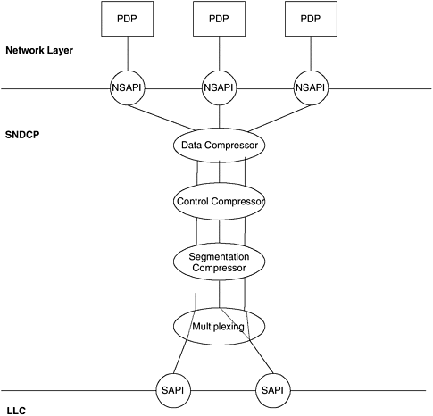
In Figure 8-8 the terms NSAPI and SAPI are used and need explanation. The network service access point identifier (NSAPI) identifies the PDP using the services provided by the SNDCP. On the other hand, the SAPI identifies the point at which LLC services are provided to the upper layer. Several NSAPIs can be associated with the same SAPI, and that's how the multiplexing is provided. Figure 8-8. SNDCP functions. The SNDCP layer depends on the LLC and the SM layers for some services. The SM layer/function needs to inform the SNDCP about activation, deactivation, and modification of the PDP contexts. During inter-SGSN RA update, the SM needs to inform the SNDCP when the N-PDUs shall be tunneled to the new SGSN. LLC needs to provide in-sequence packet delivery to SNDCP so the segmentation and reassembly can be carried out correctly. It also conveys a QoS profile from the SM to the LLC for the QoS profile-based transfer of PDUs. 8.3.7 Gb InterfaceThe Gb interface connects the PCU to SGSN. It is composed of frame relay (FR), network service control (NSC), and BSSGP layers. FR provides permanent virtual connections for carrying signaling and user data. The NSC is in charge of the administration of the virtual connections and links between the SGSN and the PCUs. FR and NS transport BSSGP PDUs between a BSS and an SGSN. In R4 release, IP is also defined to carry BSSGP PDUs instead of FR. BSSGP transmits the radio- related control information between the PCU and the SGSN. This is comparable to the BSSAP function on the A interface. However, unlike BSSAP it is not limited to the transfer of control information. It also transfers user application data. BSSGP provides flow control according to the negotiated QoS level and the load situation on the Gb and the air interface. It manages virtual connections, which are called BVCs. When a user changes a cell, the SGSN informs the BSSGP in PCU. The PCU then either redirects or deletes the buffered LLC frames depending on the transmission mode. 8.3.8 LLCThe LLC layer provides the logical link for transfer of data between an MS and its SGSN. This layer contains all the radio-specific functions. It was designed for an RF-independent purpose, thus making the upper layers of GPRS independent of the radio interface. The LLC layer provides services to the layer 3 protocols, such as GMM and SM, using service access points (SAPs). An LLC layer connection is identified by the DLCI, which consists of the SAPI and the MS's TLLI. The TLLI is given to the LLC by the GMM. Each LLC frame consists of the header, trailer, and information field. The header and trailer fields contain control information such as SAPI, frame number, and checksum. The control information is used to identify the frame and to provide reliable transmission. LLC can provide more than one logical link connection per user. It also provides ciphering and deciphering of the information fields. LLC supports unacknowledged and acknowledged modes of operation. In the unacknowledged mode, it does not guarantee in-order delivery. It also does not provide error recovery procedures for a received erroneous frame. The unacknowledged mode is known as asynchronous disconnected mode (ADM). The GMM, SM, and SMS applications use the ADM. Some user data transfer can also use ADM. In the acknowledged mode, peer entities of LLC provide a balanced data link. Each entity assumes responsibility for the organization and error recovery of the data flow it originates. This mode of operation is known as asynchronous balanced mode (ABM) and provides a reliable service with inorder delivery. The acknowledged mode is only allowed for the transfer of user data. |
EAN: 2147483647
Pages: 164
- Integration Strategies and Tactics for Information Technology Governance
- Measuring ROI in E-Commerce Applications: Analysis to Action
- Technical Issues Related to IT Governance Tactics: Product Metrics, Measurements and Process Control
- The Evolution of IT Governance at NB Power
- Governance Structures for IT in the Health Care Industry
