8.4 Radio Functions
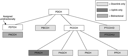
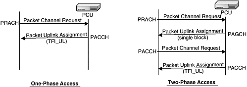
| This section describes the logical channel structure, coding scheme, RLC/MAC, and procedures for GPRS. The description is intended to give an overview of the enhancements made in the radio functions for data, without going into detail. 8.4.1 Physical and Logical Radio ChannelsThe physical channel dedicated to the packet data traffic is called the packet data channel (PDCH). The packet data logical channels are mapped onto PDCH. The logical channels consist of different types based on the functions they perform. Figure 8-9 shows the various PDCHs. Figure 8-9. Radio channel structure. PACKET COMMON CONTROL CHANNEL (PCCCH)The logical channels for common control signaling are called PCCCH. The channels under this category are the packet random access channel (PRACH), packet access grant channel (PAGCH), packet notification channel (PNCH), and packet paging channel (PPCH). The PRACH is used by MS to initiate uplink transfer for sending data or signaling information. It carries an initial network access message from the MS. The PAGCH is used to convey the assignment of dedicated uplink or downlink resources to an MS. The PNCH is used for point-to-multi-point multicast (PTM-M) service. It is used to send a PTM-M notification to a group of MSs prior to a PTM-M packet transfer. The PPCH is used to page an MS prior to downlink packet transfer. The CCCH for normal GSM can be used instead of PCCCH. Usually PCCCH is provided in a system that has significant packet data traffic. It can also be provided if there is enough bandwidth in the system to dedicate a spectrum for a set of channels just for packet traffic. This also reflects that the GPRS system can be gradually introduced to an existing GSM system. PACKET BROADCAST CONTROL CHANNEL (PBCCH)The PBCCH is used to broadcast GPRS- related system information about a cell to all the GPRS-enabled MSs that are currently camping on that cell . This information is used by the MS to access the network for packet transmission operation. In addition to the packet mode parameters, the PBCCH reproduces the circuit mode parameters from the BCCH. This allows circuit switched mode operation by an MS that is only monitoring the PBCCH. The MS after power on always reads BCCH; the BCCH conveys information about the PBCCH (i.e., whether it exists or not). PACKET DATA TRAFFIC CHANNEL (PDTCH)PDTCH is the bearer channel allocated for packet data transfer. It is unidirectional and is assigned separately for uplink and downlink directions. It is temporarily dedicated to one MS or to a group of MSs in the PTM-M case. In the multislot operation, one MS may use multiple PDTCHs in parallel for individual packet transfer. The multislot PDTCH can only be assigned on the same carrier. The PDTCH can be released after the guard timer expires due to inactivity, or after the Ack/Nack of all the sent radio blocks. PACKET DEDICATED CONTROL CHANNEL (PDCCH)The PDCCH is a control channel allocated to an MS. There are two types of channels under PDCCH: packet associated control channel (PACCH) and packet timing advance control channel uplink/downlink (PTCCH/U and PTCCH/D). The PACCH conveys signaling information related to a given MS. The signaling information includes acknowledgments and power control information. PACCH also carries resource assignment and reassignment messages, comprising the assignment of a capacity for PDTCH(s) and for further occurrences of PACCH. PACCH shares resources with PDTCHs that are currently assigned to one MS. Additionally, an MS that is currently involved in packet transfer can be paged for circuit switched services on PACCH. The PTCCH is used to derive the correct value for timing advance that the MS has to use for the uplink transmission of radio blocks. The PTCCH/U is used to transmit a random access burst to allow estimation of the timing advance for one MS in packet transfer mode. PTCCH/D is used to transmit timing advance information updates to several MSs. One PTCCH/D is paired with several PTCCH/Us. 8.4.2 Channel Coding SchemeFor offering higher throughput than the traditional GSM, GPRS introduces three new coding schemes (CS-2 to CS-4). These coding schemes trade off transmission errors for throughput. All the coding schemes (CS-1 to CS-4) are mandatory for GPRS MS. Only CS-1 is mandatory for the network. The network chooses the coding scheme for an MS. The coding procedure adds a block check sequence (BCS) for error detection. It also adds precoding USF (except for CS-1), four tail bits, and a half-rate convolutional coding for error correction. The error correction is not done for CS-4. The data rates, including RLC header and information, for CS-1, CS-2, CS-3, and CS-4 are 9.05, 13.4, 15.6, and 21.4 Kbps, respectively. On the other hand, for EGPRS nine modulation and coding schemes, MCS-1 to MCS-9, are defined for PDTCH. For all EGPRS packet control channels the corresponding GPRS control channel coding is used. A link adaptation mechanism is provided that selects the best coding scheme based on the channel conditions. The mechanism performs the measurement on the channel quality. If the channel quality is good, a high-rate CS is used because less amount of coding is needed for error correction and detection. On the other hand, if the channel quality is bad, a low-rate CS is used. 8.4.3 RLC/MACThe RLC and MAC layer operates above the radio physical layer. Let's briefly look into the radio physical interface for GPRS. For details, please refer to GSM TS 03.64. GPRS uses TDMA technology, where one carrier frequency is divided into eight time slots. A TDMA frame is a radio frame containing bursts for the eight time slots. GPRS uses a 52-multiframe structure, where each frame is a TDMA frame. The GRPS resource allocation is done on the block level. The four consecutive appearances of the same time slot within four consecutive TDMA frames is termed as one radio block. Therefore, the 52- multiframe offers 12 radio blocks, leaving 4 TDMA frames for the control information. The RLC/MAC procedures define how to utilize these radio blocks. The RLC/MAC layer messages and signaling procedures are defined in GSM TS 04.60. The GPRS radio interface uses temporary block flow (TBF) as a notion for RR allocation. TBF is a physical connection used by the two RR entities. It is used to support the unidirectional transfer of LLC PDUs on packet data physical channels. TBF is similar to a channel number in CS transactions. A TBF is identified by a 5-bit temporary flow identity (TFI). The TFI is assigned in a resource assignment message that precedes the transfer of LLC frames belonging to one TBF to/from the MS. In GPRS, the packet data transactions are unidirectional. Therefore, the assigned TFI is unique in each direction. The same TFI value may be used concurrently for TBFs in opposite directions but on different PDCHs. The lifetime of a TBF is limited to the lifetime of the related packet data transaction. The RLC function provides the procedures for a bitmap selective retransmission of unsuccessfully delivered RLC data blocks. The RLC/MAC function provides two modes of operation: unacknowledged and acknowledged . The RLC function provides segmentation and reassembly of LLC-PDUs into RLC data blocks. It also provides link adaptation according to the channel conditions. The MAC layer defines the procedures that enable multiple MSs to share a common transmission medium over the air interface. This medium may consist of several physical channels. For mobile-originated channel access, the MAC function provides arbitration between multiple MSs attempting to transmit simultaneously and provides collision avoidance , detection, and recovery procedures. The arbitration is provided in the uplink direction with the help of the uplink state flag (USF) bits sent in each downlink RLC block. The USF field identifies the user of the next uplink block on the same time slot. For mobile- terminated channel access, MAC provides scheduling of access attempts, including queuing of packet access. MAC also provides efficient multiplexing of data and control signaling in both uplink and downlink directions. The control of multiplexing resides on the PCU. On the downlink, multiplexing is controlled by a scheduling mechanism. On the uplink, multiplexing is controlled by the resource allocation mechanism. The MAC also handles priority of different transaction in its functions. RLC/MAC offers a variety of procedures for different functions. In the following sub-sections we look into RLC/MAC functions only in conjunction with mobile-originated and mobile-terminated packet transfer. MOBILE-ORIGINATED PACKET TRANSFERThe initial access by an MS is performed by sending a packet channel request message on PRACH. PRACH is used when a PCCCH is provided in a cell. If only CCCH is available, the MS could send a regular GSM channel request message on the RACH to initiate packet access. The GPRS offers two different network access methods (Figure 8-10): Figure 8-10. Access methods using packet channel only. Source: ETSI 2002. Further use, modification, and redistribution is strictly prohibited . ETSI standards are available from http://pda.etsi.org/pda/ and http://www.ets.org/eds/.
In one-phase access, the packet channel request is responded to by the network, with the packet uplink assignment reserving the resources on PDCH(s) for uplink transfer of a number of RLC/MAC data blocks. One-phase access needs a contention resolution mechanism because the packet channel request message cannot uniquely identify the sending MS. Another MS may consider the same resource allocation to be destined to itself and start using it. For contention resolution, the first thing the network does is include the TLLI in the RLC header while the contention is being resolved. In this way the MS that sent the request can identify its radio blocks. The second thing the network does is declare who owns the allocation. This is done by inclusion of the TLLI in the packet uplink ack/nack message. If there is a second mobile station using the same uplink resource, it needs to stop its transmission immediately. In the two-phase access, the packet uplink assignment is sent by the network, granting only a single block on the uplink path to specify its resource requirements and to identify itself. Two-phase access is always used when the access is performed on RACH. This is because on RACH there are only two cause values available for denoting GPRS request. These cause values are not sufficient to specify completely the requested resource. On PRACH, the MS can specify more information about the requested resources. The MS sends a packet resource request message, specifying itself by TLLI and its resource requirement. The network also has the authority to deny one-phase access and enforce two-phase access by allocating only a single block, irrespective of the RACH access. If the network has received more packet channel requests than it can serve, it can send a packet queuing notification to the sender of the packet channel request. The notification provides a mechanism for queuing the request for a short time. GPRS provides four types of resource allocation:
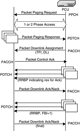
FIXED ALLOCATION ¢ In fixed allocation, the PCU sends a fixed time slot assignment and a block assignment bitmap per time slot to the MS. The bitmap represents the assigned blocks within several consecutive 52-multiframes where the MS may transmit. The network also conveys a start frame to the MS indicating when to start the transmission. If the current allocation is not sufficient, the MS may request additional resources in one of the assigned uplink blocks. DYNAMIC ALLOCATION ¢ The dynamic method can serve packet transmission more efficiently by allocating radio blocks to different MSs based on priority. This method is based on the use of the USF. The USF is a 3-bit field and is part of the MAC header of each downlink RLC data block that is sent. The USF of a downlink block identifies who is going to use the next uplink block on the same time slot. An MS involved in a multislot assignment could have different USFs assigned, one for each time slot. The MS shall monitor the USF on each PDCH in the list of assigned PDCHs, up to and including the first PDCH currently used for transmission. This monitoring is one of the disadvantages of the method because an MS has to decode all the downlink data blocks to find their USF. EXTENDED DYNAMIC ALLOCATION ¢ This method is helpful in multislot assignment. It relieves the multislot MS from listening to all downlink blocks on all the assigned time slots to find its USF. This is achieved by setting specific rules for the allocation. The descriptions for the rules are available in GSM TS 03.64. The MS follows the rules in order to understand its uplink allocation. EXCLUSIVE ALLOCATION ¢ Exclusive allocation does not use the USF and the block assignment bitmap. The MS is free to transmit on the uplink without monitoring the downlink for the USF. In exclusive allocation, the network conveys a start frame and a slot assignment in the assignment message. The MS waits until the start frame and then starts transmitting the radio blocks on the assigned slots. Unused USF values may be used to prevent other mobiles from transmitting on those frames. The uplink TBF is released by using the countdown procedure. The same procedure is used for all types of resource allocation. The mobile initiates the countdown procedure, but the TBF release is confirmed by the network. The procedure uses a 4-bit parameter, called countdown value (CV), in the uplink RLC/MAC radio blocks. CV indicates how many RLC/MAC data blocks are remaining to be transmitted by the MS. When the network sees CV=0, it sends a packet uplink ack message with the final ack indicator bit set to 1. It also allocates an uplink radio block, using the RRBP field, for the final control message from the MS. MOBILE TERMINATED PACKET TRANSFERA mobile in MM-STANDBY state is paged by sending a packet paging request message from the PCU to the MS (Figure 8-11). The packet paging request is sent on PPCH or PCH. The MS responds to one packet paging request message by initiating a mobile-originated packet transfer request. This mobile-originated packet transfer allows the MS to send a packet paging response to the network. The network then assigns radio resources to the MS and performs the downlink data transfer. Figure 8-11. Mobile-terminated packet transfer. The PCU allocates PDCH(s) and informs the MS by sending a packet downlink assignment message. If the MS is engaged in an uplink packet transfer, the message is transmitted on PACCH. Otherwise the packet is transferred on PCCCH. If the PCCCH is not allocated in the cell, the message is transmitted on CCCH. The RLC/MAC blocks destined for different MSs can be multiplexed on the same PDCH. The MSs recognize their blocks by identifying TFI. The MS may need to issue control messages, either packet downlink ack or packet control ack, in the uplink direction. The downlink TBF doesn't provide uplink resources to the MS. The solution is that the network needs to allocate a single uplink block to a given MS dynamically. This is done by using a 2-bit-long parameter, relative reserved block period (RRBP), to identify the uplink block. RRBP is part of each RLC/MAC data and control block in downlink direction and allocates a single radio block in uplink direction to the addressed MS. For releasing the downlink TBF, the network sets the final block indicator (FBI) bit to 1 in the RLC header, indicating that this block is the last to be sent. Within the same block, the network allocates a single uplink block by using RRBP to the MS to confirm proper reception or to require retransmission in acknowledged mode. The MS sends a packet downlink ack message. In unacknowledged RLC mode, the mobile confirms the TBF release by issuing a packet control ack. |
EAN: 2147483647
Pages: 164


