Decomposition Style
2.1.1 Overview
By taking the elements and the properties of the module viewtype and focusing on the is-part-of relation, we get the module decomposition style. You can use this style to show how system responsibilities are partitioned across modules and how those modules are decomposed into submodules. Unlike other styles of the module viewtype, decomposition features fairly weak restrictions on the viewtype itself but is usefully distinguished as a separate style, for several reasons.
First, almost all architectures begin with the module decomposition style. Architects tend to attack a problem with divide-and-conquer techniques, and a view rendered in this style records their campaign. Second, a view in this style is a favorite tool with which to communicate the broad picture of the architecture to newcomers. Third, this style begins to address the modifiability that will be built into the architecture by allocating functionality to specific places in the architecture.
The criteria used for decomposing a module into smaller modules depend on the purpose of the decomposition:
- Achievement of certain quality attributes. For example, to support modifiability, the information-hiding design principle calls for encapsulating changeable aspects of a system in separate modules, so that the impact of any one change is localized. Another example is performance. Separating functionality that has higher performance requirements from other functionality enables application of different strategies, such as scheduling policies or judicious assignment to processors, to achieve required performance throughout the various parts of the system.
- Build-versus-buy decisions. Some modules may be bought in the commercial marketplace or reused intact from a previous project and therefore already have a set of functionality implemented. The remaining functionality then must be decomposed around those established modules.
- Product line implementation. To support the efficient implementation of products of a product family, it is essential to distinguish between common modules, used in every or most products, and variable modules, which differ across products.
A decomposition view may represent the first pass at a detailed architectural design; the architect may subsequently introduce other style-based specializations and evolve the view resulting from decomposition into a more detailed use, layered, or other module-based view in some other style.
2.1.2 Elements, Relations, and Properties
Table 2.1 summarizes the discussion of the characteristics of the decomposition style. Elements of the decomposition style are modules, as described in Section 1.2. Certain aggregations can be called subsystems. The principal relation, the decomposition relation, is a specialized form of the is-part-of relation and has as its primary constraint the guarantee that an element can be a part of at most one aggregate.
The decomposition relation may have a visibility property, which defines whether the submodules are visible to only the aggregate modulethe parentor also to other modules. A module is said to be visible if it can be used by other modules. With this property, an architect has some control over the visibility of modules, as illustrated in Figure 1.1. A decomposition relation in which no contained module is visible outside its parent is sometimes called a containment relation. In a decomposition relation, loops are not allowed; that is, a module cannot contain any of its ancestors. No module in a decomposition view can have more than one parent.
| Elements | Module, as defined by the module viewtype. A module that aggregates other modules is sometimes called a subsystem. |
| Relations | The decomposition relation, which is a refined form of the is-part-of relation. A documentation obligation includes specifying the criteria used to define the decomposition. |
| Properties of elements | As defined by the module viewtype. |
| Properties of relations | Visibility, the extent to which the existence of a module is known, and its facilities are available, to those modules outside its parent. |
| Topology |
|
2.1.3 What the Decomposition Style Is For and What It's Not For
A decomposition style view presents the functionality of a system in intellectually manageable pieces that are recursively refined to convey more and more details. Therefore, this style is well suited to support the learning process about a system. Besides the obvious benefit for the architect to support the design work, this style is an excellent learning and navigation tool for newcomers in the project or other people who do not necessarily have the whole functional structure of the system memorized. The grouping of functionality shown in this style also builds a useful basis for defining configuration items within a configuration management framework.
The decomposition style most often serves as the input for the work assignment view of a system, which maps parts of a software system onto the organizational units, or teams, that will be given the responsibility for implementing and testing them. A decomposition view also provides some support for analyzing effects of changes at the software implementation level, but because this view does not show all the dependencies among modules, you cannot expect to do a complete impact analysis. Here, views that elaborate the dependency relationships more thoroughly, such as the module uses style described later, are required.
2.1.4 Notations for the Decomposition Style
Informal Notations
In informal notations, modules in the decomposition style are usually depicted as named boxes that contain other named boxes. Containment can also be shown using indentation, as in Figure 2.2.
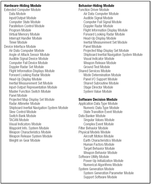
Figure 2.2. The decomposition of the A-7E software architecture results in three modules and is-part-of relations (Bass, Clements, Kazman, 2001, p. 61).
The nesting notation can use a thick border suggesting opaquenessand explained in the keyindicating that children are not visible outside the parent. Similarly, various kinds of arcs can be used to indicate containment, or nonvisibility, as opposed to an ordinary is-part-of relation. If a visual notation is not available for indicating visibility, it can be defined textually, as is done for other properties, especially the modules' responsibilities.
UML
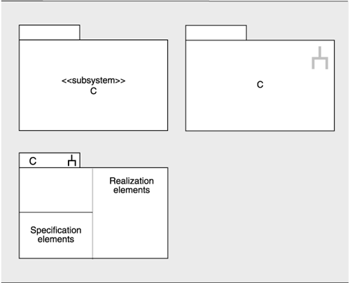
In UML, the subsystem construct can be used to represent modules that contain other modules; the class box is normally used for the leaves of the decomposition. Subsystems are both a package and a classifier. As a package, they can be decomposed and hence are suitable for the aggregation of modules. As a classifier, they encapsulate their contents and can provide an explicit interface.
In UML, aggregation is depicted in one of three ways:
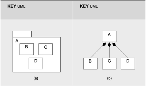
- Modules may be nested, as in Figure 2.1(a).
Figure 2.1. In UML, aggregation may be shown by (a) nesting, with the aggregate module shown as a package, or by (b) using arcs between the parent and the children. The solid diamond indicates the parent module.
- A succession of two diagrams, possibly linked, can be shown, with the second a depiction of the contents of a module shown in the first.
- An arc denoting composition may be drawn between the parent and the children, as in Figure 2.1(b). In UML, composition is a form of aggregation with implied strong ownership. That is, parts live and die with the whole. If module A is composed of modules B and C, for example, B or C cannot exist without the presence of A. If A is destroyed at runtime, so are B and C. Thus, UML's composition relation has implications beyond the structuring of the implementation units; the relation also endows the elements with a runtime property. As an architect, you should make sure that you are comfortable with this property before using UML's composition relation.
Other properties, such as the modules' responsibilities, are given textually, perhaps using an annotation.
2.1.5 Relation to Other Styles
It is possible, and often desirable, to map between a module decomposition view and a component-and-connector view. We discuss this in greater detail later. For now, it is sufficient to say that the point of providing such a mapping is to indicate how the software implementation structures map onto runtime structures: generally, a many-to-many relationship. The same module might implement several components or connectors. Conversely, one component might require several modules for its implementation. The mapping may be fairly straightforward or quite complex.
The decomposition style is closely related to the work assignment style, a member of the allocation viewtype. The work assignment style maps modules resulting from a decomposition to a set of teams responsible for implementing and testing those modules.
2.1.6 Examples of the Decomposition Style
ECS
Appendix A contains an example of a module decomposition view for NASA's ECS system.
A-7E Avionics System
An example of the decomposition style comes from the A-7E avionics software system described in Bass, Clements, and Kazman 1998, Chapter 3. Figure 2.2 shows the graphical part of the view. The figure names the elements and shows the is-part-of relation among them for the A-7E system.
Except for the modules' names, however, the figure shows none of the properties associated with this style. Supporting the figure is textual documentation that explains the decomposition criteria and for each module lists
- Its responsibilities
- Its visibility to other modules outside its parent
- Implementation information
In this example, the criterion for decomposition is the information-hiding principle, which holds that there should be a module to encapsulate the effects each kind of change considered likely. A module's responsibilities, then, are described in terms of the information-hiding secrets it encapsulates.
In A-7E, the first-order decomposition produced three modules: hardware hiding, behavior hiding, and software decision hiding. Each of these modules is decomposed into two to six submodules, which are in turn decomposed, and so forth, until the granularity is fine enough to be manageable. A useful design heuristic holds that a module is small enough if it could be discarded and begun again if the programmer(s) assigned to implement it left the project.
The A-7E module view documentation describes the responsibilities of the three highest-level modules as follows:
- Hardware-Hiding Module: The Hardware-Hiding Module includes the procedures that need to be changed if any part of the hardware is replaced by a new unit with a different hardware/software interface but with the same general capabilities. This module implements "virtual hardware" or an abstract device that is used by the rest of the software. The primary secrets of this module are the hardware/software interfaces. The secondary secrets of this module are the data structures and algorithms used to implement the virtual hardware.
- Behavior-Hiding Module: The Behavior-Hiding Module includes procedures that need to be changed if there are changes in requirements affecting the required behavior. Those requirements are the primary secret of this module. These procedures determine the values to be sent to the virtual output devices provided by the Hardware-Hiding Module.
- Software Decision Module: The Software Decision Module hides software design decisions that are based upon mathematical theorems, physical facts, and programming considerations such as algorithmic efficiency and accuracy. The secrets of this module are not described in the requirements document. This module differs from the other modules in that both the secrets and the interfaces are determined by software designers. Changes in these modules are more likely to be motivated by a desire to improve performance or accuracy than by externally imposed changes.
Following is how the documentation describes the decomposition of the Software Decision Module into second-level modules. Unless otherwise indicated, a module is visible outside its parent:
- Application Data Type Module: The Application Data Type Module supplements the data types provided by the Extended Computer Module with data types that are useful for avionics applications and do not require a computer dependent implementation. Examples of types include distance (useful for altitude), time intervals, and angles (useful for latitude and longitude). These data types are implementedusing the basic numeric data types provided by the Extended Computer; variables of those types are used just as if the types were built into the Extended Computer. The secrets of the Application Data Type Module are the data representation used in the variables and the procedures used to implement operations on those variables. Units of measurements (such as feet, seconds, or radians) are part of the representation and are hidden. Where necessary, the modules provide conversion operators, which deliver or accept real values in specified units.
- Data Banker Module: Most data are produced by one module and consumed by another. In most cases, the consumers should receive a value as up-to-date as practical. The time at which a datum should be recalculated is determined both by properties of its consumer (e.g., accuracy requirements) and by properties of its producer (e.g., cost of calculation, rate of change of value). The Data Banker Module acts as a "middleman" and determines when new values for these data are computed. The Data Banker obtains values from producer procedures; consumer procedures obtain data from Data Banker access procedures. The producer and consumers of a particular datum can be written without knowing when a stored value is updated. In most cases, neither the producer nor the consumer need be modified if the updating policy changes.
The Data Banker provides values for all data that report on the internal state of a module or on the state of the aircraft. The Data Banker also signals events involving changes in the values that it supplies. The Data Banker is used as long as consumer and producer are separate modules, even when they are both submodules of a larger module. The Data Banker is not used if consumers require specific members of the sequence of values to be computed by the producer, or if a produced value is solely a function of the values of input parameters given to the producing procedure (such as sin(x)). The Data Banker is an example of the use of the blackboard architectural style. The choice among updating policies should be based on consumers' accuracy requirements, how often consumers require the value, the maximum wait that consumers can accept, how rapidly the value changes, and the cost of producing a new value. This information is part of the specification given to the implementor of the Data Banker.
- Filter Behavior Module: The Filter Behavior Module contains digital models of physical filters. They can be used by other procedures to filter potentially noisy data. The primary secrets of this module are the models used for the estimation of values based on sample values and error estimates. The secondary secrets are the computer algorithms and data structures used to implement those models.
- Physical Models Module: The software requires estimates of quantities that cannot be measured directly but can be computed from observables using mathematical models. An example is the time that a ballistic weapon will take to strike the ground. The primary secrets of the Physical Models Module are the models; the secondary secrets are the computer implementations of those models.
- Software Utility Module: The Software Utility Module contains those utility routines that would otherwise have to be written by more than one other programmer. The routines include mathematical functions, resource monitors, and procedures that signal when all modules have completed their power-up initialization. The secrets of the module are the data structures and algorithms used to implement the procedures.
- System Generation Module: The primary secrets of the System Generation Module are decisions that are postponed until system-generation time. These include the values of system generation parameters and the choice among alternative implementations of a module. The secondary secrets of the System Generation Module are the method used to generate a machine-executable form of the code and the representation of the postponed decisions. The procedures in this module do not run on the on-board computer; they run on the computer used to generate the code for the on-board system.
In the case of the A-7E architecture, this second-level module structure was enshrined in many ways: Design documentation, online configuration-controlled files, test plans, programming teams, review procedures, and project schedule and milestones all were pegged to this second-level module structure as their unit of reference. If you use a module decomposition structure to organize your project, you need to pick a level of the hierarchy as was done here, based on a granularity of modules that is manageable. The module guide describes a thirdand in some cases a fourthlevel of decomposition, but that has been omitted here.
Mil-Std 498 CSCIs and CSCs
Readers familiar with U.S. military software standards, such as MIL-STD-498 and MIL-STD-2167A, will recognize that CSCIs (Computer Software Configuration Items), and CSCs (Computer Software Components) constitute a decomposition view of a system and nothing more. A CSCI is an aggregation of software that satisfies an end use function and is designated for separate configuration management by the acquirer. CSCIs are selected based on trade-offs among software function, size, host or target computers, developer, support concept, plans for reuse, criticality, interface considerations, the need to be separately documented and controlled, and other factors. A CSC is a distinct part of a CSCI and may be further decomposed into other CSCs and CSUs (Computer Software Units).
Software Architectures and Documentation
- P.1. The Role of Architecture
- P.2. Uses of Architecture Documentation
- P.3. Interfaces
- P.4. Views
- P.5. Viewtypes and Styles
- P.6. Seven Rules for Sound Documentation
- P.7. Summary Checklist
- P.8. Discussion Questions
- P.9. For Further Reading
Part I. Software Architecture Viewtypes and Styles
The Module Viewtype
- Overview
- Elements, Relations, and Properties of the Module Viewtype
- What the Module Viewtype Is For and What Its Not For
- Notations for the Module Viewtype
- Relation to Other Viewtypes
- Summary Checklist
- Discussion Questions
- For Further Reading
Styles of the Module Viewtype
- Styles of the Module Viewtype
- Decomposition Style
- Uses Style
- Generalization Style
- Layered Style
- Summary Checklist
- Discussion Questions
- For Further Reading
The Component-and-Connector Viewtype
- Overview
- Elements, Relations, and Properties of the C&C Viewtype
- What the C&C Viewtype Is For and What Its Not For
- Relation to Other Viewtypes
- Summary Checklist
- Discussion Questions
- For Further Reading
Styles of the Component-and-Connector Viewtype
- Styles of the Component-and-Connector Viewtype
- The Pipe-and-Filter Style
- Shared-Data Style
- Publish-Subscribe Style
- Client-Server Style
- Peer-to-Peer Style
- Communicating-Processes Style
- Notations for C&C Styles
- Summary Checklist
- Discussion Questions
- For Further Reading
The Allocation Viewtype and Styles
- Overview
- Elements, Relations, and Properties of the Allocation Viewtype
- Deployment Style
- Implementation Style
- Work Assignment Style
- Summary Checklist
- Discussion Questions
- For Further Reading
Part II. Software Architecture Documentation in Practice
- Part II. Software Architecture Documentation in Practice
- ECS Architecture Documentation Roadmap
- ECS System Overview
- ECS Software Architecture View Template
- Mapping Between Views
- Directory
- Architecture Glossary and Acronym List
- Module Decomposition View
- Module Uses View
- Module Generalization View
- Module Layered View
- C&C Pipe-and-Filter View
- C&C Shared-Data View
- C&C Communicating-Processes View
- Allocation Deployment View
- Allocation Implementation View
- Allocation Work Assignment View
Advanced Concepts
- Advanced Concepts
- Chunking Information: View Packets, Refinement, and Descriptive Completeness
- Using Context Diagrams
- Combined Views
- Documenting Variability and Dynamism
- Creating and Documenting a New Style
- Summary Checklist
- Discussion Questions
- For Further Reading
Documenting Software Interfaces
- Overview
- Interface Specifications
- A Standard Organization for Interface Documentation
- Stakeholders of Interface Documentation
- Notation for Interface Documentation
- Examples of Interface Documentation
- Summary Checklist
- Discussion Questions
- For Further Reading
Documenting Behavior
- Beyond Structure
- Where to Document Behavior
- Why to Document Behavior
- What to Document
- How to Document Behavior: Notations and Languages
- Summary Checklist
- Discussion Questions
- For Further Reading
Choosing the Views
- Choosing the Views
- Stakeholders and Their Documentation Needs
- Making the Choice
- Two Examples
- Summary Checklist
- Discussion Questions
- For Further Reading
Building the Documentation Package
- Building the Documentation Package
- One Document or Several?
- Documenting a View
- Documentation Beyond Views
- Validating Software Architecture Documentation
- Summary Checklist
- Discussion Questions
- For Further Reading
Other Views and Beyond
- Other Views and Beyond
- Overview
- Rational Unified Process/Kruchten 4+1
- UML
- Siemens Four Views
- C4ISR Architecture Framework
- ANSI/IEEE-1471-2000
- Data Flow and Control Flow
- RM-ODP
- Where Architecture Documentation Ends
- A Final Word
- For Further Reading
- Appendix A. Excerpts from a Software Architecture Documentation Package
- Volume I ECS Software Architecture Documentation Beyond Views
Rationale, Background, and Design Constraints
References
EAN: 2147483647
Pages: 152
