Section 5.2. Manipulating Graphic Elements
5.2. Manipulating Graphic ElementsFlash offers you a gazillion tools to modify the drawings that make up your animations. You can stack, rearrange and reposition each individual graphic element, transform (shrink and squish) them, move them, apply color effects, and more until you're completely satisfied with the way they look. It's a clich, but it's true: When it comes to drawing in Flash, you're pretty much limited only by your imagination . This section acquaints you with the most powerful tools Flash offers for modifying the lines, shapes , bitmaps, symbols, and other graphic elements you add to your drawings. 5.2.1. Modifying Object PropertiesFlash's Property Inspector is a beautiful thing. Select any element on the Stage, and the Property Inspector responds by displaying all the characteristics, or properties , that you can change about that element. In Figure 5-15, for example, you see several graphic elements on the Stage: a painted fill, a bitmap of a frog, a line of text, and a star. When you select the star, the Property Inspector shows all the properties associated with the star: the color, width, and type of outline, the fill color, and so on. When you select the text, the Property Inspector changes to reflect only text properties. Note: If you don't see the Property Inspector, choose Windows  Properties and, in the pop-up menu that appears, turn on the checkbox next to Properties. If you still dont see it, check to see whether you've expanded your Stage and pushed it out of the way or collapsed the Property Inspector. Properties and, in the pop-up menu that appears, turn on the checkbox next to Properties. If you still dont see it, check to see whether you've expanded your Stage and pushed it out of the way or collapsed the Property Inspector. You can change any of the object properties you see in the Property Inspector. For example, in the Property Inspector on the left side of Figure 5-15, you can change the color, width, or style of the star's outline color. (You can change all these properties by using Flash's selection and drawing tools, too, of course, but using the Property Inspector is a lot quicker for most changes.) Figure 5-15. Selecting an object tells Flash to display that object's properties right there at the bottom of the work area in the Property Inspector. Here, the star shape's selected, so the properties all relate to this particular star. As long as the property isn't grayed out, you can change it in the Property Inspector.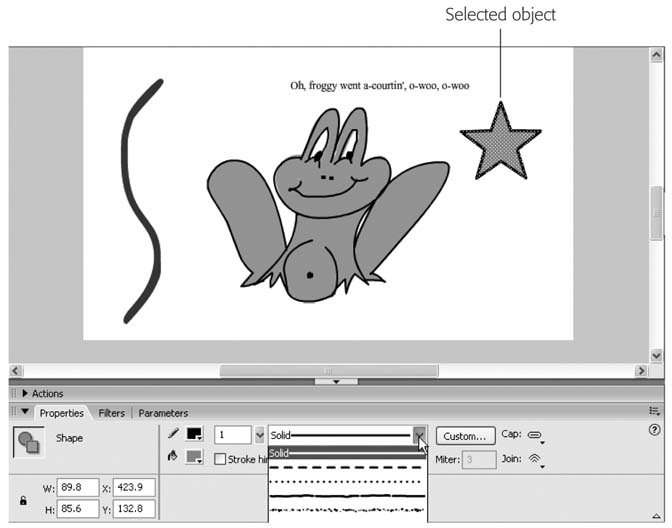 5.2.2. Moving, Cutting, Pasting, and CopyingAfter you have an object on the Stage, you can move it around, cut it (delete it), paste it somewhere else, or make copies of it. Tip: All the things you can do to an objectcutting, pasting, copying, and movingyou can also do to a piece of an object. Instead of selecting the entire object, just select whatever portion of the object you want to work with and go from there. 5.2.2.1. MovingTo move an object, simply select it (Section 5.1) and then drag it around the Stage. Figure 5-16 shows an example of using the Selection tool to select a group of objects and move them together. 5.2.2.2. Cutting To cut an object, select the object (Section 5.1) and then choose Edit Note: Choosing Edit Clear deletes the select object, too, but doesnt enable the Paste functions. In other words, after you choose Edit Clear, its gone, baby, gone (unless you quickly choose Edit Undo Delete). 5.2.2.3. Copying To copy an object, select the object and then choose Edit Tip: You can perform a quick copy-and-paste operation by selecting an object and then choosing Edit Duplicate. Flash displays a movable copy of the selected object just above the selected object. 5.2.2.4. Pasting To paste an object that you've either cut or copied , choose one of the following:
5.2.3. Transforming Objects (Scaling, Rotating, Skewing, Distorting)In the graphics world, transforming an object doesn't just mean changing the object; transforming means applying very specific shape and size changes to the object. These changescalled transforms include:
You have three choices when it comes to applying a transform to a selected object (or group of objects):
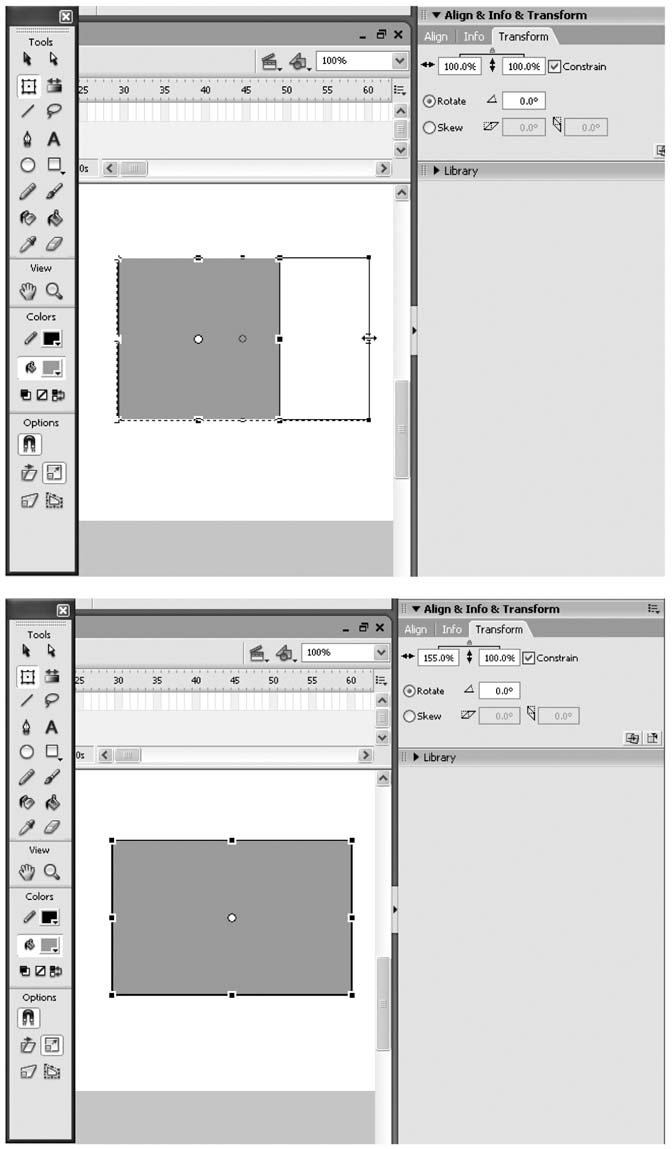
Figure 5-17. Flash gives you three different ways to apply transforms: using the main menu, the Transform panel, and the Free Transform tool. In the sections that follow, you see the Free Transform tool in action.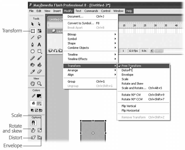 5.2.3.1. Scaling objectsTo resize a drawn object, first select the object on the Stage, then proceed as follows :
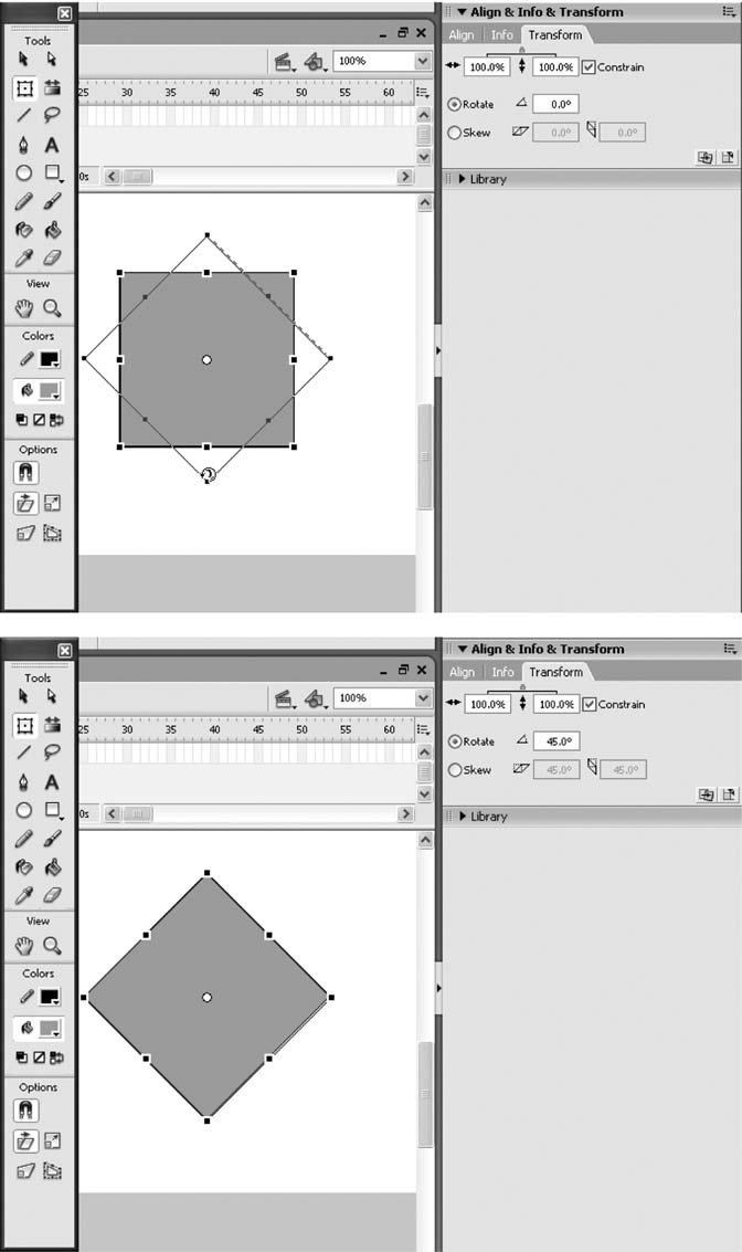
5.2.3.2. Rotating objectsTo rotate a drawn object around its axis, first select the object on the Stage, then proceed as follows:
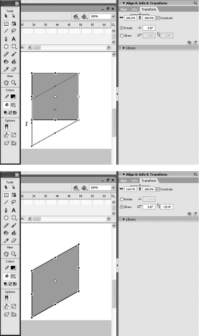
Tip: You can most easily rotate a selected object 180 degrees (upside down or left-to-right ) by selecting Modify Transform Flip Vertical or Modify Transform Flip Horizontal. 5.2.3.3. Skewing objects To give your drawing a slanted shape, first select the object on the Stage, then proceed as follows:
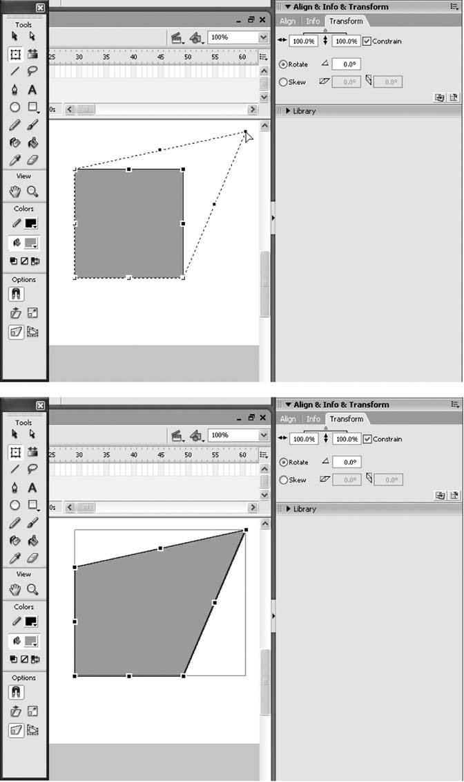
5.2.3.4. Distorting objectsFor more freedom than simple skewing, you can distort your drawn objects in any way or direction:
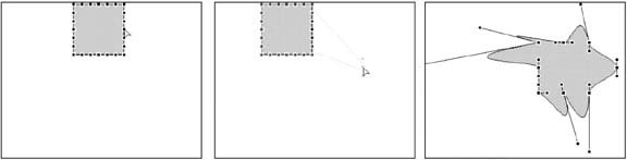
Tip: Shift-dragging a corner point lets you taper a shape; that is, move that corner and the adjoining corner apart from each other an equal distance. 5.2.3.5. Applying an envelope transformAs discussed on Section 5.2.3.1, an envelope transform is the most radical distortion. It gives you more distortion points than the regular Distort option, and also gives you finer control over the points by letting you drag inward or outward to create rounded bulges or dents (not just pointy ones). Here's how to use the Envelope distortion.
You see the results of modifying several distortion points in Figure 5-22 (right). Figure 5-22. Left: After you select the Envelope option, mousing over any of the black squares or circles at the sides and corners of your object displays a distortion arrow. |
| WORKAROUND WORKSHOP Safety in Groups |
| If you plan to move your graphic elements around a lotstack them, unstack them, and reposition them on the Stagemake sure you create them in object drawing mode (Section 2.2.1.3), which tells Flash to group each object individually. If you want to stick with merge drawing mode (because it's the only way Flash let you draw pre-Version 8 and you're used to it, for example), draw your objects on a fresh, clean corner of the Stage and then group them individually yourself. Here's why. Say you're working in merge drawing mode and you create a rectangle on the Stage using Flash's Rectangle drawing tool. What you've really created are two separate animals: a rectangular fill, and a rectangular outline, or stroke. If you want to select the entire rectangle, outline and all, you need to drag the Selection tool to surround the entire rectanglewhich is a problem if you didn't draw your rectangle on a fresh part of the Stage and your rectangle happens to be sitting on top of another shape. Selection is no problem, you say? Well, try dragging your selected (ungrouped) rectangle and dropping it onto another ungrouped shape, such as a circle. When you go to move the circle, you see that it's no longer a circle at all: Flash has taken a pair of scissors to it. Here's one last reason to group your objects before you begin rearranging or moving them: Flash uses a different automatic stacking order depending on the type of objects you drag on top of each other. Whichever way Flash stacks your objects, you can change the stacking order to suit yourselfwith one exception. Flash doesn't let you place an ungrouped object on top of a grouped object or a symbolno way, no how . If you need to place an ungrouped object on top of a grouped object (or on top of a symbol), either group the ungrouped object and then restack it (to group a selected object, choose Modify |
To stack objects on the Stage:
-
Select the object you want to rearrange (either to push behind or pull in front of another object ).
In Figure 5-24 (top), the circle's selected.
-
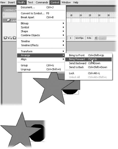
Choose Modify
Arrange and then, from the pop-up menu that appears, change the objects stacking order . Here are your options:
Bring to Front . Pulls the selected object all the way forward until it's on top of all the other objects.
Bring Forward . Pulls the selected object forward in front of just one other object.
Figure 5-23. Top: Stacking isn't an issue when your objects don't touch each other. The instant you drag one object on top of another, though, you have to decide which object you want to appear on top, and which behind.
Bottom: Flash stacks objects differently depending on the kind of objects involved. Here, Flash places the third grouped object behind the other two.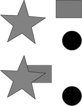
Send Backward . Pushes the object back behind just one other object.
Send Back . Pushes the selected object all the way back, until it's behind all the other stacked objects.
Figure 5-24 (bottom) shows you an example of choosing Bring Forward with the circle selected.
5.2.5. Converting Strokes to Fills
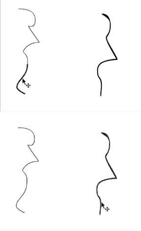
As you saw in Chapter 2 (Section 2.2.2), Flash treats lines and fills differently when you're working in merge drawing mode. For example, take a look at Figure 5-25, which shows a line drawn with the Pencil and a line drawn with the Brush.
If you click the Selection tool and then click to select the Pencil-drawn line, Flash highlights just one stroke of the line (Figure 5-25, top). But performing the very same operation on the similar-looking Brush-drawn line selects the entire Brush-drawn line (Figure 5-25, bottom).
When you convert a line into a fill, Flash lets you interact with the line just as you would with any other fill. This technique is especially useful when you're working with shapes, no matter which drawing mode you're using. That's because when you create a shape using one of Flash's shape toolsa star, say, or a circleFlash actually creates two separate elements: the inside of the shape (a fill), and the outline of the shape (a stroke). If you want to change the color of the entire shape, you need to use two tools: the Paint Bucket tool (which lets you change the color of fills), and the Ink Bottle tool (which lets you change the color of strokes). When you convert the outline to a fill, Flash lets you manipulate both the outside and the inside of the shape in the same way using the same tools. Converting also lets you create scalable shapes (images that shrink evenly) and nice straight corners (thick strokes appear rounded at the corners; thick fills shaped like lines don't).
Figure 5-24. Top: To restack an object, you need to select it first. Here, you see the circle selected.
Bottom: Choosing Bring Forward brings the selected object (the circle) forward one position in the stacking order. To bring the circle all the way to the front, choose Bring to Front.
To convert a line into a fill:
-
Select the line (or outline) you want to convert into a fill .
Flash highlights the selected line.
-
Choose Modify
Shape Convert Lines to Fills . Flash redisplays the line as a fill, and the Property Inspector changes to display fill-related properties (as opposed to line- related properties).
5.2.6. Aligning Objects
In Chapter 2 (Section 2.2.1.3), you saw how to use Flash's grid, guides, and rulers to help you eyeball the position of objects as you drag them around on the Stage. You also see how to use the Alignment panel to line up objects with respect to each other or to one of the edges of the Stage.
Figure 5-25. Top: When you're working with ungrouped objects (which is what you create in merge drawing mode), the Selection tool behaves differently. Here, you see the results of clicking the Pencil-drawn line: Flash selects only a portion of the line (a single stroke).
Bottom: Clicking the Brush-drawn line, on the other hand, selects the entire line. This behavior is just one example of the different way Flash treats strokes and fills.
Both these approaches are usefulbut Flash doesn't stop there. Snapping and guide layers give you even more control over where you place your objects with respect to each other on the Stage.
5.2.6.1. Snapping
Snapping is one of those features you're going to either love or hate. When you turn snapping on, you tell Flash to help you out when you're moving an object around by giving you a visual cue when you start to get too close to (or actually touch) a gridline, a guideline, or another object.
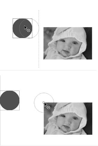
For example, in Figure 5-26, you see a circle being dragged across the Stage. Because Snap Align is turned on, Flash displays a faint dotted line (top) when the circle's dragged within range of the other object on the Stage (in this case, a bitmap image). And because "Snap to Objects" is turned on, Flash displays a thick o at the very center of the object as it's dragged over the edge of the bitmap (Figure 5-26, bottom).
Figure 5-26. Top: When you turn on snapping, Flash gives you a visual cue when you drag one object close to another object: a gridline or a guideline. Here, Snap Align's turned on, so Flash displays a dotted line when the circle's dragged near the bitmap. You tell Flash how close is close enough using the Horizontal and Vertical Object Spacing fields of the Edit Snapping window, which you display by choosing View Snapping Edit Snapping and then, in the Edit Snapping window that appears, clicking Advanced.
Bottom: In this example, Snap to Objects is turned on, too, so if you continue dragging past the dotted line, you see another helpful hint: Flash displays a circle when you center the circle directly over the bitmaps edge.
Tip: For snapping to work, you can't speed around the Stage; if you do, you'll miss Flash's cues. Instead, drag your objects slowly.
To turn on snapping, select View Snapping and then, from the context menu that appears, choose one of the following:
-
Snap Align . Displays a dotted line when you drag an object within a certain number of pixels (you see how to change this number in the box on the next page) of another object or of any edge of the Stage.
-
Snap to Grid . Displays a small, thick circle in the middle of your object when you drag that object close to a gridline (Section 2.2.1.3).
-
Snap to Guides . Displays a small, thick circle in the middle of your object when you drag that object close to a guideline (Section 2.2.1.3).
-
Snap to Pixels . Useful only if you want to work at the single-pixel level (your Stage must be magnified to at least 400 percent for this option to work), this option prevents you from moving an object in any increment less than a whole pixel. (To magnify your Stage by 400 percent, select View
Magnification 400%; when you do, a single-pixel grid appears.) -
Snap to Objects . Displays a small, thick circle in the middle of your object when you drag that object close to another object on the Stage.
The next time you move an object on the Stage, Flash displays the snapping behavior you chose.
| FREQUENTLY ASKED QUESTION Object Snapping: How Close Is Too Close? |
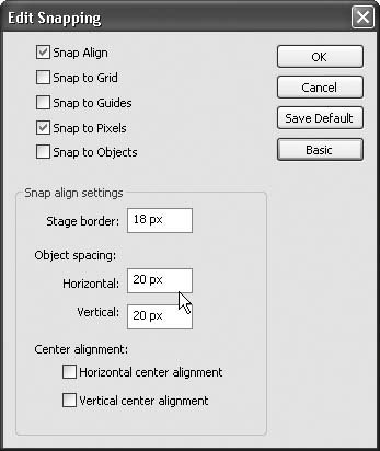
| Everybody says Snap Align is so great, but I'm not sure why I'd use it or how close I should set the snapping range . Whether or not you'll find Snap Align useful depends entirely on you (some folks prefer to freewheel it, while others appreciate hints and advice) and what you're trying to create on the Stage. Snap Align is most useful in situations where you're trying to custom-position objects down to the pixel. For example, say you've drawn a row of different- sized flowers, and you're trying to position a row of bees, one bee at a time, exactly 25 pixels above the flowers. You can use the Align panel for a lot of basic alignment tasks , but this kind of custom alignment isn't one of them: Snap Align's your best option. Flash assumes a buffer zone of 10 pixels around objects and 18 pixels around each edge of the Stage. (In other words, when you drag an object within 10 pixels of another object or 18 pixels from the edge of the Stage, Flash displays a snap guideline.) To change either of these buffer zones:
 |
5.2.6.2. Guide layers
If you've ever traced a drawing onto a piece of onionskin paper, you understand the usefulness of guide layers in Flash.
A guide layer is a special kind of layer that doesn't appear in your finished animation, but that you can hold beneath your Stage while you're drawing to help you position objects on the Stage. Say, for example, you want to align objects in a perfect circle, or on a perfect diagonal, or you want to arrange them so that they match a specific background (say, an ocean scene). You create a guide layer and, on it, draw your circle or diagonal or ocean scene. Then, when you create your "real" layer, your guide layer shows through so you can position your objects the way you want them. When you go to run your animation, though, you don't see your guide layer at all; it appears only when you're editing on the Stage.
Note: Technically speaking, a guide layer is a motion guide layer (just without the motion). You learned more about motion guide layers in Chapter 3.
To create a guide layer:
-
On the Stage, draw your guide shapes, lines, or images .
In Figure 5-27 (top), the guide's a diagonal line.
-
Position your cursor over the name of the layer you want to turn into a guide layer and then right-click .
Flash displays a pop-up menu.
-
From the pop-up menu, select Guide .
Flash displays a little T-square just before the layer name, as in Figure 5-27 (bottom).
Figure 5-27. Top: First, draw your guide. You can import a bitmap (useful if you want to display a background image as your guide) or use any of Flash's drawing tools. Here, the guide's a simple diagonal line.
Bottom: To tell Flash that this layer's going to be a special, only-see-it-while-you're-editing guide layer, right-click the layer name and then, from the menu that appears, select Guide. After you do, Flash designates a guide layer by displaying the little T-square icon in front of the layer name (here, Layer 1).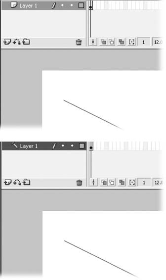
-
With the guide layer still selected, create a new, regular layer for your objects by choosing Insert
Timeline Layer . Flash creates a new layer and places it above the guide layer, as in Figure 5-28 (top).
Tip: Working with layersespecially guide layerscan be confusing if you're not used to it (and, frankly, it can be confusing even if you are used to it, especially if you're working with a lot of layers). To make sure you don't inadvertently modify your guide layer, you can lock it (tell Flash not to let you edit it temporarily). To lock your guide layer, click to select it and then turn on the checkbox beneath the Lock/Unlock column. Then, when you click to select your regular layer, you can align away without worrying about accidentally changing your (locked) guide layer.
-
Select View
Snapping and, in the context menu that appears, turn on the checkbox next to "Snap to Objects." Youve turned snapping on . Turning snapping on helps you position your objects on your guide layer.
-
With the regular layer selected, draw your objects .
You can then drag each object to your guideline (or guide object, or guide background) as shown in Figure 5-28 (bottom).
EAN: 2147483647
Pages: 126