2-10 area area-id range ip-address mask not-advertise
| < Free Open Study > |
2-10 area area-id range ip-address mask not-advertiseSyntax Description:
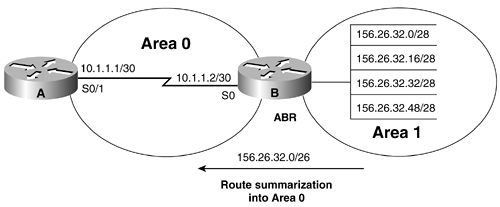
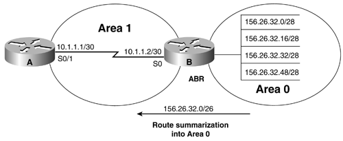
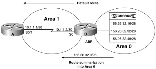
Purpose: OSPF can summarize OSPF routes from the backbone or Area 0 into a non-zero OSPF area or from a non-zero area into the backbone. OSPF route summarization can only occur on an ABR. An ABR is a router than has at least one interface in Area 0 and at least one interface in a non-zero OSPF area. Commands 2-8 and 2-9 are equivalent. Using the keyword not-advertise will suppress the advertisement of the summary route by the ABR. Initial Cisco IOS Software Release: 10.0 Configuration Example 1: Summarizing OSPF Routes from a Non-zero OSPF Area into the BackboneIn Figure 2-8, Router B will summarize the four Area 1 routes into Area 0. This example simulates four networks on Router B using loopback interfaces. These four networks will then be summarized into the backbone using the area range command. Figure 2-8. An ABR Can Summarize OSPF Routes from a Non-zero Area into the Backbone or Area 0 Router A interface Loopback0 ip address 1.1.1.1 255.255.255.255 ! interface Serial0/1 ip address 10.1.1.1 255.255.255.252 clockrate 64000 ! router ospf 1 network 10.1.1.0 0.0.0.3 area 0 _______________________________________________________________________ Router B interface Loopback0 ip address 2.2.2.2 255.255.255.255 ! interface Loopback1 ip address 156.26.32.1 255.255.255.240 ! interface Loopback2 ip address 156.26.32.17 255.255.255.240 ! interface Loopback3 ip address 156.26.32.33 255.255.255.240 ! interface Loopback4 ip address 156.26.32.49 255.255.255.240 ! interface Serial0 ip address 10.1.1.2 255.255.255.252 ! router ospf 1 network 10.1.1.0 0.0.0.3 area 0 network 156.26.32.0 0.0.0.63 area 1 Before summarizing the routes, inspect the IP routing table on Router A to verify that the four networks are being advertised. rtrA# show ip route Codes: C - connected, S - static, I - IGRP, R - RIP, M - mobile, B - BGP D - EIGRP, EX - EIGRP external, O - OSPF, IA - OSPF inter area N1 - OSPF NSSA external type 1, N2 - OSPF NSSA external type 2 E1 - OSPF external type 1, E2 - OSPF external type 2, E - EGP i - IS-IS, L1 - IS-IS level-1, L2 - IS-IS level-2, * - candidate default U - per-user static route, o - ODR Gateway of last resort is not set 1.0.0.0/32 is subnetted, 1 subnets C 1.1.1.1 is directly connected, Loopback0 156.26.0.0/32 is subnetted, 4 subnets O IA 156.26.32.33 [110/65] via 10.1.1.2, 00:06:57, Serial0/1 O IA 156.26.32.49 [110/65] via 10.1.1.2, 00:06:57, Serial0/1 O IA 156.26.32.1 [110/65] via 10.1.1.2, 00:06:57, Serial0/1 O IA 156.26.32.17 [110/65] via 10.1.1.2, 00:06:57, Serial0/1 10.0.0.0/30 is subnetted, 2 subnets C 10.1.1.0 is directly connected, Serial0/1 A 26-bit subnet mask is required to summarize the four loopback addresses being advertised by Router B. Modify the configuration on Router B in order to summarize the four loopback addresses. Router B router ospf 1 area 1 range 156.26.32.0 255.255.255.192 network 10.1.1.0 0.0.0.3 area 0 network 156.26.32.0 0.0.0.63 area 1 There are two important components to notice in the area range command. The first is the area ID. This is the area where the routes originated. In this example, the originating area is Area 1. The second component is the mask that is used with the area range command. The format of the mask is the opposite of the format used with the OSPF network command. VerificationVerify that the four loopback networks have been summarized by Router B by inspecting the IP routing table on Router A. rtrA# show ip route Codes: C - connected, S - static, I - IGRP, R - RIP, M - mobile, B - BGP D - EIGRP, EX - EIGRP external, O - OSPF, IA - OSPF inter area N1 - OSPF NSSA external type 1, N2 - OSPF NSSA external type 2 E1 - OSPF external type 1, E2 - OSPF external type 2, E - EGP i - IS-IS, L1 - IS-IS level-1, L2 - IS-IS level-2, * - candidate default U - per-user static route, o - ODR Gateway of last resort is not set 1.0.0.0/32 is subnetted, 1 subnets C 1.1.1.1 is directly connected, Loopback0 156.26.0.0/26 is subnetted, 1 subnets O IA 156.26.32.0 [110/65] via 10.1.1.2, 00:04:57, Serial0/1 10.0.0.0/30 is subnetted, 2 subnets C 10.1.1.8 is directly connected, Serial0/0 C 10.1.1.0 is directly connected, Serial0/1 Configuration Example 2: Summarizing OSPF Routes from Area 0 into a Non-zero OSPF AreaIn Figure 2-9, Router B will summarize the four Area 0 routes into Area 1. This example simulates four networks on Router B using loopback interfaces. These four networks will then be summarized into Area 1 from Area 0 using the area range command. The configuration changes from the previous example are highlighted in the following listing. Figure 2-9. An ABR Can Summarize OSPF Routes from the Backbone or Area 0 into a Non-Zero Area Router A interface Loopback0 ip address 1.1.1.1 255.255.255.255 ! interface Serial0/1 ip address 10.1.1.1 255.255.255.252 clockrate 64000 ! router ospf 1 network 10.1.1.0 0.0.0.3 area 1 _______________________________________________________________________ Router B interface Loopback0 ip address 2.2.2.2 255.255.255.255 ! interface Loopback1 ip address 156.26.32.1 255.255.255.240 ! interface Loopback2 ip address 156.26.32.17 255.255.255.240 ! interface Loopback3 ip address 156.26.32.33 255.255.255.240 ! interface Loopback4 ip address 156.26.32.49 255.255.255.240 ! interface Serial0 ip address 10.1.1.2 255.255.255.252 ! router ospf 1 network 10.1.1.0 0.0.0.3 area 1 network 156.26.32.0 0.0.0.63 area 0 Before summarizing the routes, inspect the IP routing table on Router A to verify that the four networks are being advertised. rtrA# show ip route Codes: C - connected, S - static, I - IGRP, R - RIP, M - mobile, B - BGP D - EIGRP, EX - EIGRP external, O - OSPF, IA - OSPF inter area N1 - OSPF NSSA external type 1, N2 - OSPF NSSA external type 2 E1 - OSPF external type 1, E2 - OSPF external type 2, E - EGP i - IS-IS, L1 - IS-IS level-1, L2 - IS-IS level-2, * - candidate default U - per-user static route, o - ODR Gateway of last resort is not set 1.0.0.0/32 is subnetted, 1 subnets C 1.1.1.1 is directly connected, Loopback0 156.26.0.0/32 is subnetted, 4 subnets O IA 156.26.32.33 [110/65] via 10.1.1.2, 00:06:29, Serial0/1 O IA 156.26.32.49 [110/65] via 10.1.1.2, 00:06:29, Serial0/1 O IA 156.26.32.1 [110/65] via 10.1.1.2, 00:06:29, Serial0/1 O IA 156.26.32.17 [110/65] via 10.1.1.2, 00:06:29, Serial0/1 10.0.0.0/30 is subnetted, 2 subnets C 10.1.1.8 is directly connected, Serial0/0 C 10.1.1.0 is directly connected, Serial0/1 A 26-bit subnet mask is required to summarize the four loopback addresses being advertised by Router B. Modify the configuration on Router B in order to summarize the four loopback addresses. Router B router ospf 1 area 0 range 156.26.32.0 255.255.255.192 network 10.1.1.0 0.0.0.3 area 1 network 156.26.32.0 0.0.0.63 area 0 VerificationVerify that the four loopback networks have been summarized by Router B by inspecting the IP routing table on Router A. rtrA# show ip route Codes: C - connected, S - static, I - IGRP, R - RIP, M - mobile, B - BGP D - EIGRP, EX - EIGRP external, O - OSPF, IA - OSPF inter area N1 - OSPF NSSA external type 1, N2 - OSPF NSSA external type 2 E1 - OSPF external type 1, E2 - OSPF external type 2, E - EGP i - IS-IS, L1 - IS-IS level-1, L2 - IS-IS level-2, * - candidate default U - per-user static route, o - ODR Gateway of last resort is not set 1.0.0.0/32 is subnetted, 1 subnets C 1.1.1.1 is directly connected, Loopback0 156.26.0.0/26 is subnetted, 1 subnets O IA 156.26.32.0 [110/65] via 10.1.1.2, 00:04:57, Serial0/1 10.0.0.0/30 is subnetted, 2 subnets C 10.1.1.8 is directly connected, Serial0/0 C 10.1.1.0 is directly connected, Serial0/1 Configuration Example 3: Using a Static Route to Null 0 for the Summary AddressIf the ABR has a default static route pointing to the router that is receiving the summary for the four loopback addresses, then this could create a forwarding loop. In Figure 2-10, the network 156.26.32.0/28 is down. Also, Router B has a default static route pointing to Router A. Router A is receiving a summary from Router B that contains the network 156.26.32.0/28. Figure 2-10. A Forwarding Loop Can Be Created If the Router Advertising the Summary Has a Default Static Route Router A interface Loopback0 ip address 1.1.1.1 255.255.255.255 ! interface Serial0/1 ip address 10.1.1.1 255.255.255.252 clockrate 64000 ! router ospf 1 network 10.1.1.0 0.0.0.3 area 1 ______________________________________________________________________ Router B interface Loopback0 ip address 2.2.2.2 255.255.255.255 ! interface Loopback1 ip address 156.26.32.1 255.255.255.240 shutdown ! interface Loopback2 ip address 156.26.32.17 255.255.255.240 ! interface Loopback3 ip address 156.26.32.33 255.255.255.240 ! interface Loopback4 ip address 156.26.32.49 255.255.255.240 ! interface Serial0 ip address 10.1.1.2 255.255.255.252 no ip directed-broadcast ! router ospf 1 network 10.1.1.0 0.0.0.3 area 1 network 156.26.32.0 0.0.0.63 area 0 ! ip route 0.0.0.0 0.0.0.0 Serial0 When Router A sends traffic to Router B for host 156.26.32.1, Router B will not find this specific network in the IP routing table. Router B will then use the default route and send the traffic back to Router A as seen in the following ping trace. rtrA# trace 156.26.32.1 Type escape sequence to abort. Tracing the route to 156.26.32.1 1 10.1.1.2 16 msec 16 msec 16 msec 2 10.1.1.1 28 msec 28 msec 28 msec To prevent this situation, create a static route to Null0 for every summary that the ABR is advertising. In IOS 12.X, OSPF will automatically create the route to Null0 for the summary. Router B ip route 0.0.0.0 0.0.0.0 Serial0 ip route 156.26.32.0 255.255.255.192 Null0 Even if the ABR does not have a default route, it is always a good idea to create a static route to Null0 for every summary that the ABR is advertising. If you now perform a ping trace from Router A you can see that Router B is discarding the traffic since the specific route for 156.26.32.1 is no longer in the IP routing table. Router B will look up the best match for the route, which is now Null0. The traffic will be discarded. rtrA# trace 156.26.32.1 Type escape sequence to abort. Tracing the route to 156.26.32.1 1 10.1.1.2 16 msec 16 msec 16 msec 2 10.1.1.2 !H !H * Troubleshooting
|
| < Free Open Study > |
EAN: 2147483647
Pages: 236


