Creating Custom Line Types
As your drawing needs expand, the standard line types might not be adequate for your application. Fortunately, you can create your own. This section explains how to do so.
You'll get an in-depth view of the process of creating line types. You'll also learn how to create complex line types that cannot be created by using the Express Make Linetype tool.
Viewing Available Line Types
Although AutoCAD provides the line types most commonly used in drafting (see Figure 20.2), the dashes and dots might not be spaced the way you would like, or you might want an entirely new line type.
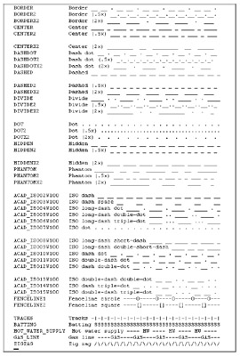
Figure 20.2: The lines in this list of standard line types were generated with the underscore key (_) and the period (.) and are only rough representations of the actual lines.
| Tip | AutoCAD stores the line types in a file called Acad.lin , which is in ASCII format. When you create a new line type, you are adding information to this file. Or, if you create a new file containing your own line-type definitions, it too will have the extension .lin. You can edit line types as described here or you can edit them directly in these files. |
To create a custom line type, use the Linetype command. Let's see how this handy command works, by first listing the available line types:
-
Open a new AutoCAD file.
-
At the command prompt, enter “Linetype
 . (Don't forget the minus sign at the beginning.)
 -
At the Enter an option [?/Create/Load/Set]: prompt, enter ?
. -
In the dialog box, locate and double-click Acad in the listing of available line-type files. You get the list shown in Figure 20.2, which shows the line types available in the Acad.lin file along with a simple description of each line. Figure 20.2 shows a complete view of the standard line types and the ISO and complex line types. Figure 20.3 shows how some of the line types look in a drawing or when they are plotted.
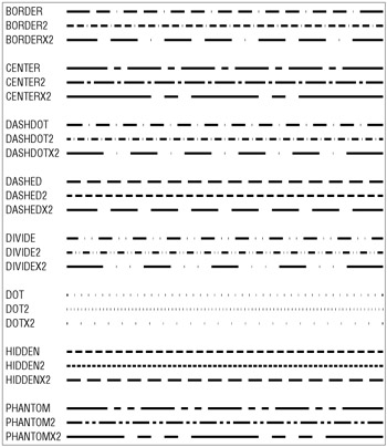
Figure 20.3: Some of the more commonly used standard AutoCAD line types as they appear when plotted
Creating a New Line Type
Next , let's try creating a new line type:
-
At the ?/Create/Load/Set: prompt, enter C
. -
At the Enter name of linetype to create: prompt, enter Custom
as the name of your new line type. -
The dialog box you see next is named Create Or Append Linetype File. You need to enter the name of the line-type file you want to create or add to. If you pick the default line-type file, Acad, your new line type is added to the Acad.lin file. If you choose to create a new line-type file, AutoCAD opens a file containing the line type you create and adds .lin to the filename you supply.
-
Let's assume you want to start a new line-type file. Enter Newline
in the File Name input box. Tip If you accept the default line-type file, Acad, the prompt in step 5 is Wait, checking if linetype already defined . This protects you from inadvertently overwriting an existing line type you want to keep.
-
At the Descriptive text: prompt, enter a text description of your line type. You can use any keyboard character as part of your description, but the actual line type can be composed of only a series of lines, points, and blank spaces. For this exercise, enter
Custom - My own center line __________ _ ____________
using the underscore key (_) to simulate the appearance of your line.
-
At the Enter linetype pattern (on next line): prompt, enter the following numbers , known as the line-type code (after the a that appears automatically):
1.0,-.125,.25,-.125
Warning If you use the Set option of the “Linetype command to set a new default line type, you will get that line type no matter what layer you are on.
-
At the New definition written to file . Enter an option [?/Create/Load/Set]: prompt, press
to exit the “Linetype command.
Remember, after you've created a line type, you must load it in order to use it, as discussed in Chapter 4.
| Tip | You can also open the Acad.lin or other .lin file in Windows Notepad and add the descriptive text and line-type code directly to the end of the file. |
Understanding the Line-Type Code
In step 6 of the previous exercise, you entered a series of numbers separated by commas. This is the line-type code, representing the lengths of the components that make up the line type. The separate elements of the line-type code are as follows :
-
The 1.0 following the a is the length of the first part of the line. (The a that begins the line- type definition is a code that is applied to all line types.)
-
The first “ .125 is the blank or broken part of the line. The minus sign tells AutoCAD that the line is not to be drawn for the specified length, which is 0.125 units in this example.
-
Next comes the positive value of 0.25 . This tells AutoCAD to draw a line segment 0.25 units long after the blank part of the line.
-
Finally, the last negative value, “ .125 , again tells AutoCAD to skip drawing the line for the distance of 0.125 units.
This series of numbers represents the one segment that is repeated to form the line (see Figure 20.4). You can also create a complex line type that looks like a random broken line, as in Figure 20.5.
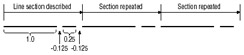
Figure 20.4: Line section described with plotted line
You might be wondering what purpose the a serves at the beginning of the line-type code. A line type is composed of a series of line segments and points. The a , which is supplied by AutoCAD automatically, is a code that forces the line type to start and end on a line segment rather than on a blank space in the series of lines. At times, AutoCAD stretches the last line segment to force this condition, as shown in Figure 20.6.
| Tip | The values you enter for the line-segment lengths are multiplied by the Ltscale factor; so be sure to enter values for the plotted lengths. |
Figure 20.5: Random broken line
Figure 20.6: AutoCAD stretches the beginning and the end of the line as necessary.
As mentioned in the beginning of this section, you can also create line types outside AutoCAD by using a word processor or text editor such as Windows Notepad. The standard Acad.lin file looks like Figure 20.3 with the addition of the code used by AutoCAD to determine the line-segment lengths.
Normally, to use a line type you have created, you have to load it, through either the Layer or the Linetype dialog box (choose Format Layers or Format Linetype). If you use one of your own line types frequently, you might want to create a button macro so it will be available as an option on a menu.
Creating Complex Line Types
A complex line type is one that incorporates text or special graphics. For example, if you want to show an underground gas line in a site plan, you normally show a line with the intermittent word GAS, as in Figure 20.7. Fences are often shown with an intermittent circle, square, or X .
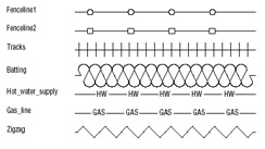
Figure 20.7: Samples of complex line types
For the graphics needed to compose complex line types, use any of the symbols found in the AutoCAD font files discussed in Chapter 8. Just create a text style by using these symbol fonts, and then specify the appropriate symbol by using its corresponding letter in the line-type description.
To create a line type that includes text, use the same line-type code described earlier, with the addition of the necessary font file information in brackets. For example, say you want to create the line type for the underground gas line mentioned previously by using just the letter G . You add the following to your Acad.lin file:
*Gas_line_G -- G --
Ga,1.0,-0.25, ["G", standard, S=.2, R=0, X=-.1, Y=-.1], -0.25
The information in the square brackets describes the characteristics of the text. The actual text that you want to appear in the line is surrounded by quotation marks. Next are the text style, scale, rotation angle, X displacement, and Y displacement.
| Warning | You cannot use the “Linetype command to define complex line types. Instead, you must open the Acad.lin file by using a text editor, such as Windows Notepad, and add the line-type information to the end of the file. Make sure you don't duplicate the name of an existing line type. |
You can substitute A for the rotation angle (the R value), as in the following example:
a,1.0,-0.25, ["G", standard, S=.2 A=0, X=-.1, Y=-.1], -0.25
This has the effect of keeping the text at the same angle, regardless of the line's direction. Notice that in this sample, the X and Y values are a -.1; this will center the G s on the line. The scale value of .2 will cause the text to be 0.2 units high, so the - .1 is half the height.
In addition to fonts, you can also specify shapes for line-type definitions. Instead of letters , shapes display symbols. Shapes are stored not as drawings, but as definition files, similar to text-font files. In fact, shape files have the same .shx filename extension as text files and are also defined similarly. Figure 20.8 shows some symbols from shape files supplied with the companion CD. The names of the files are shown at the top of each column.
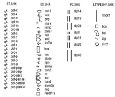
Figure 20.8: Samples of shapes available on the companion CD
To use a shape in a line-type code, you use the same format as shown previously for text. However, instead of using a letter and style name, you use the shape name and the shape filename, as in the following example:
*Capline, ====
a,1.0,-0.25,[CAP,ES.SHX,S=.5,R=0,X=-.1,Y=-.1],-0.25
This example uses the CAP symbol from the Es.shx shape file. The symbol is scaled to 0.5 units with 0 rotation and an X and Y displacement of “0.1.
Here is another example that uses the arrow shape:
*Arrowline, --------
a,1.0,-0.25,[ARROW,ES.SHX,S=.5,R=90,X=-.1,Y=-.1],-0.25
Just as with the Capline example, the ARROW symbol in this example is scaled to 0.5 units with 0 rotation, and an X and Y displacement of “0.1. Here's what the Arrowline line type looks like when used with a spline.
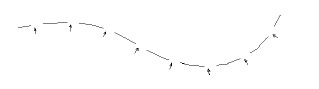
In this example, the Ltype generation option is turned on for the polyline. Note that the arrow from the Es.shx sample shape file is used for the arrow in this line type.
EAN: 2147483647
Pages: 261