Creating Hatch Patterns
AutoCAD provides several predefined hatch patterns you can choose from (see Figure 20.9), but you can also create your own. This section demonstrates the basic elements of pattern definition.
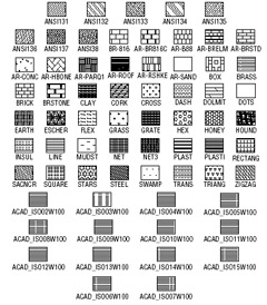
Figure 20.9: The standard hatch patterns
Unlike line types, hatch patterns cannot be created while you are in an AutoCAD file. The pattern definitions are contained in an external file named Acad.pat . You can open and edit this file with a text editor that can handle ASCII files, such as Windows Notepad. Here is one hatch pattern definition from that file:
*square,Small aligned squares
0, 0,0, 0,.125, .125,-.125
90, 0,0, 0,.125, .125,-.125
You can see some similarities between pattern descriptions and line-type descriptions. They both start with a line of descriptive text and then give numeric values defining the pattern. However, the numbers in pattern descriptions have a different meaning. This example shows two lines of information. Each line represents a line in the pattern. The first line determines the horizontal line component of the pattern, and the second line represents the vertical component. Figure 20.10 shows the hatch pattern defined in the example.
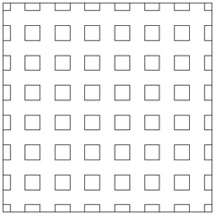
Figure 20.10: A square pattern
A pattern is made up of line groups. A line group is like a line type that is arrayed a specified distance to fill the area to be hatched. A line group is defined by a line of code, much as a line type is defined. In the square pattern, for instance, two lines ”one horizontal and one vertical ”are used. Each of these lines is duplicated in a fashion that makes the lines appear as boxes when they are combined. Figure 20.11 illustrates this point.
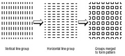
Figure 20.11: The individual and combined line groups
Look at the first line in the definition:
0, 0,0, 0,.125, .125,-.125
This example shows a series of numbers separated by commas; it represents one line group. It actually contains four sets of information, separated by blank spaces:
-
The first component is the at the beginning. This value indicates the angle of the line group, as determined by the line's orientation. In this case, it is for a horizontal line that runs from left to right.
-
The next component is the origin of the line group, 0,0 . This does not mean that the line begins at the drawing origin (see Figure 20.12). It gives you a reference point to determine the location of other line groups involved in generating the pattern.
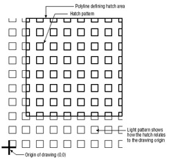
Figure 20.12: The origin of the patternsTip If you have forgotten the numeric values for the various directions, refer to Chapter 2, which explains AutoCAD's system for specifying angles.
-
The next component is 0,.125 . This determines the distance and direction for arraying the line, as illustrated in Figure 20.13. This value is like a relative coordinate indicating X and Y distances for a rectangular array. It is not based on the drawing coordinates, but on a coordinate system relative to the orientation of the line. For a line oriented at a 0 ° angle, the code 0,.125 indicates a precisely vertical direction. For a line oriented at a 45 ° angle, the code 0,.125 represents a 135 ° direction. In this example, the duplication occurs 90 ° in relation to the line group, because the X value is . Figure 20.14 illustrates this point.
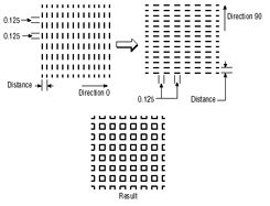
Figure 20.13: The distance and direction of duplication -
The last component is the actual description of the line pattern. This value is equivalent to the value given when you create a line type. Positive values are line segments, and negative values are blank segments. This part of the line-group definition works exactly as in the line-type definitions you studied in the previous section.
This system of defining hatch patterns might seem somewhat limiting, but you can do a lot with it. Autodesk managed to come up with 69 patterns ”and that was really only scratching the surface.
| Tip | If you want to include thick lines in your hatch patterns, you have to "build up" line widths with multiple line-type definitions. |
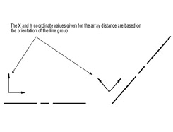
Figure 20.14: How the direction of the line group copy is determined
EAN: 2147483647
Pages: 261