Enhancing the 2D Drawing Process
Using solids to model a part ”such as the Bracket and the Solidedit examples used in this chapter ” might seem a bit exotic, but there are definite advantages to modeling in 3D, even if you want to draw the part in only 2D as a page in a set of manufacturing specs .
The exercises in this section show you how to quickly generate a typical mechanical drawing from your 3D model by using Paper Space and the Solids toolbar. You will also examine techniques for dimensioning and including hidden lines.
| Tip | If your application is architecture, and you've created a 3D model of a building by using solids, you can use the tools described in this section to generate 2D elevation drawings from your 3D solid model. |
Drawing a Standard Top, Front, and Right-Side View
One of the more common types of mechanical drawings is the orthogonal projection. This style of drawing shows separate top, front, and right-side views of an object. Sometimes a 3D image is also added for clarity. You can derive such a drawing within a few minutes, after you create your 3D solid model. The first step is to select a sheet title block. The title block consists of a border and an area in the lower-right corner for notes and other drawing information.
| Tip | If you need to refresh your memory about using Paper Space, refer to Chapter 12. |
Setting Up a File with a Title Block
The first step is to create a file by using one of AutoCAD's template files designed for mechanical applications:
-
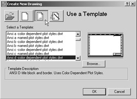
If you haven't done so already, save the Bracket.dwg file from the earlier exercise, and then Choose File New to open the Create New Drawing dialog box. If you do not see the Create New Drawing dialog box, select Ansi D- Color Dependent Plot Styles.dwt from the Select Template dialog box which appear in place of the Create New Drawing dialog box, and then skip to step 4.
-
Click the Use A Template button.
-
Scroll down the Select A Template list box and select Ansi d-color dependent plot styles.dwt . A title block appears, along with a viewport to Model Space.
-
This template contains a predefined layout viewport that you don't need for this exercise. Click the inside border of the title block to select the viewport; then press the Delete key.
Warning If for some reason you do not see a listing of template files in the Create New Drawing dialog box, you will need to set up AutoCAD to look for these files in the right place. Normally, AutoCAD looks in the C:\Documents and Settings\ User Name \Local Settings\Application Data\Autodesk\AutoCAD 2005\R16.1\enu\Template folder for template files. Check the Template Drawing File Location listing in the Files tab of the Options dialog box. See Appendix B for details.
-
Choose View Viewports 1 Viewport, and then click two diagonal points to add a single rectangular viewport a little larger than the one shown in Figure 18.42. (However, you won't see anything in the viewport yet.)
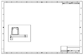
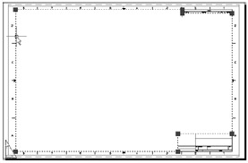
Figure 18.42: Resizing the view- port so it is just large enough to contain the view of the bracket -
Choose File Save As to save this file as Bracket_title.dwg .
You are now in Floating Model Space. Though it might not be obvious at first glance, the title block is in Paper Space, and an active Model Space viewport is inside the title block.
Importing the 3D Model
The next step is to insert the Bracket solid model into this drawing. Remember that while you are in a floating Model Space viewport, anything you do affects Model Space. So in the next exercise, you will use the Insert tool to import the Bracket drawing into the Model Space of this new drawing:
-
Double-click inside the new viewport to make it active, and then choose Insert Block to open the Insert dialog box.
-
Click the Browse button to open the Select Drawing File dialog box.
-
Locate and select the Bracket.dwg file and then click Open.
-
Back in the Insert dialog box, make sure that the Explode check box is selected. If the Specify On-Screen option in the Insertion Point group is turned on, turn it off.
-
Click OK. The drawing appears in the viewport.
You must take one more step before you actually set up the Orthogonal views. You want the current viewport to display a front view of the bracket. You can do this easily with a single menu option:
-
Choose View 3D Views Front. The Viewport view changes to show the front view of the model.
-
Choose View Zoom Scale, and then type 1
 to give the view a 1-to-1 scale. This has the same effect as setting the Standard Scale property of the viewport to a value of 1:1. The view is now in proper scale to the title block.
 -
Double-click outside the viewport or click the Model button in the status bar. Then, using its grips, resize the viewport so it is just large enough to display the model, as shown in Figure 18.42. To expose the viewport grip, click the viewport border.
-
Move the viewport to a location similar to the one shown in Figure 18.42.
Creating the Orthogonal Views
Now you are ready to create the Orthogonal views. The next part will seem simple compared with the steps you had to take to set up the title block and viewport:
-
 Click the Setup View tool on the Solids toolbar or choose Draw Solids Setup View.
 -
At the Ucs/ Ortho /Auxiliary/Section/<Exit>: prompt, type O
. -
At the Specify side of viewport to project: prompt, place the cursor on the right side of the viewport so that a Midpoint Osnap marker appears, as shown in the first image in Figure 18.43. A rubber-banding line appears.
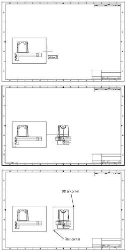
Figure 18.43: Adding the Orthogonal views in Paper Space -
At the Specify View Center: prompt, click a point to the right of the viewport, at about half the width of the viewport. The right-side view of the bracket appears, as shown in the second image in Figure 18.43. Click again to adjust the horizontal position of the right-side view.
-
After you're satisfied with the location of the view, press
. You don't have to be too precise at this point because you will be able to adjust the view's location later. -
At the Specify first corner of viewport: prompt, click a location below and to the left of the right-side view, as shown in the final image in Figure 18.43.
-
At the Specify opposite corner of viewport: prompt, click above and to the right of the view, as shown in the final image in Figure 18.43.
-
At the Enter view name: prompt, enter rightside . Notice that the Ucs/Ortho/Auxiliary/ Section/<Exit>: prompt appears again. This enables you to set up another view.
At this point, you can exit the Setup View tool by pressing
, but you need another view. Continue with the following steps to create the top view. -
Type O
again, but this time, at the Specify side of viewport to project: prompt, click the top edge of the front-view viewport. -
Follow steps 4 through 8 to create a top view. In step 4, click a point above the viewport instead of to the right.
-
Name this third viewport Top .
-
When you return to the Ucs/Ortho/Auxiliary/Section/<Exit>: prompt, press
to exit the command.
Each new view you create by using the Setup View tool is scaled to match the original view from which it is derived. As you saw in step 3, the view that is generated depends on the side of the view- port you select. If you pick the bottom of the viewport, a bottom view is generated, which looks the same as the top view until you choose View Hide to display it as a hidden-line view.
Creating an Isometric View
In this section, you will add an Isometric view to your Paper Space layout at a 1-to-1 scale. You can use the Setup View tool to accomplish this, but you'll need to set up a UCS to which the Setup View tool can refer.
The following explains how to set up such a UCS for an Isometric view:
-
Click the Model tab to go to Model Space.
-
Choose View 3D Views SE Isometric to display an Isometric view of the model.
-
Choose Tools New UCS View to set the UCS to be parallel to the current view plane.
-
Choose Tools Named UCS to open the UCS Control dialog box.
-
Rename the current Unnamed UCS to SEIsometric.
-
Click the ANSI D title block tab to return to the Layout view of your model.
Notice that even though you changed your view in Model Space, the Paper Space viewports maintain the views as you last left them. Now you're ready to create a viewport showing the same Isometric view you set up in Model Space:
-
Click the Setup View tool on the Solids toolbar or choose Draw Solids Setup View.
-
At the Ucs/Ortho/Auxiliary/Section/<Exit>: prompt, type U
. -
At the Named/World/?/<Current>: prompt, press
to accept the current UCS. -
At the Enter view scale <1.0000>: prompt, press
to accept the scale of 1. -
At the View center: prompt, click a point above and to the right of the original viewport. The Isometric view of the model appears, as shown in Figure 18.44. If you don't like the view's location, you can continue to click points until the view's location is just where you want it.
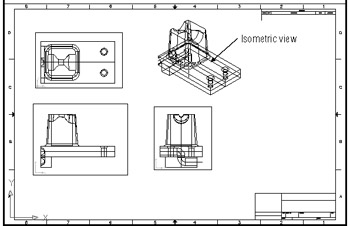
Figure 18.44: Adding a viewport for the Isometric view -
Press
when you are satisfied with the view's location. -
At the Clip First corner: prompt, place a window around the Isometric view to define the viewport border.
-
Name the view SEIsometric .
-
Press
to exit the Setup View tool.
A lot of steps were involved in creating these views. However, imagine the work involved if you had to create these views manually, and you'll appreciate the power of these few simple tools.
Creating Hidden-Line Views
You aren't quite finished yet. Typically, orthographic projections, such as the top, front, and right-side view, show the hidden portions of the model with dashed lines. For example, the holes toward the right end of the bracket would be shown dashed in the front view. You could set up the viewports to do a hidden-line removal at plot time, but this would not create the effect you want.
Fortunately, AutoCAD offers the Setup Profile tool to quickly generate a proper Orthographic Projection view of your solid model. Take the following steps to create your first hidden-line view:
-
Go to Floating Model Space by double-clicking the lower-left viewport.
-
 Choose Setup Profile from the Solids toolbar or choose Draw Solids Setup Profile.
 -
Click both halves of the solid model and then press
. -
At the Display hidden profile lines on separate layer? <Y>: prompt, press
. -
At the Project profile lines onto a plane? <Y>: prompt, press
. -
At the Delete tangential edges? <Y>: prompt, press
. AutoCAD will work for a moment, and then the command prompt will appear with no apparent change to the drawing.
You don't see the effects of the Setup Profile tool yet. You'll need to make the solid model invisible to display the work that was done by the Setup Profile tool. You'll also have to make a few layer changes to get the profile views just right. Here are the steps:
-
Double-click an area outside the viewport or click the Model button on the status bar to return to Paper Space.
-
Zoom in to the front view so it fills most of the display area.
-
Turn off Layer0 (zero). If it is the current layer, you will get a message telling you that you are about to turn off the current layer. Click OK. You've just turned off the layer of the solid model, leaving the profile created by the Setup Profile tool. Notice that you see only an image of the front view.
-
Open the Layer Properties Manager (click the Layers tool in the Object Properties toolbar or choose Format Layer).
-
Select the layer whose name begins with the PH prefix.
-
Change its line type to Hidden. You might need to load the hidden-line type.
-
After you've changed the line type, click OK to exit the Layer Properties Manager dialog box. The front view now displays hidden lines properly with dashed lines, as shown in Figure 18.45.
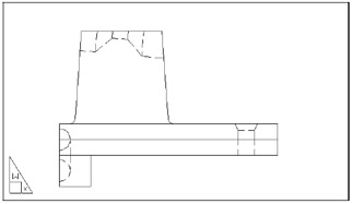
Figure 18.45: The front view after using the Setup Profile tool
The Setup Profile tool creates a 2D drawing of your 3D model. This 2D drawing is projected onto an imaginary plane that is parallel to the view from which you selected the model while using the Setup Profile tool. To see this clearly, take a look at your model in Model Space:
-
Click the Model tab to go to Model Space.
-
Turn Layer0 back on. You see the projected 2D view next to the 3D model, as shown in Figure 18.46.
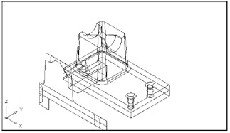
Figure 18.46: The projected view next to the 3D solid model
Shading a Viewport
In Chapter 15, you saw how you can view your 3D model as a shaded view in Model Space. The shaded view gives you a more realistic representation of your 3D model, and it can show off more of the details, especially in rounded surfaces. You can also view and plot a shaded view in a Layout tab. To do this, you make a viewport active and then turn on the shading feature you want to use for that viewport. The following exercise gives you a firsthand look at how this is done:
-
Click the Layout tab in the lower portion of the AutoCAD window.
-
Double-click inside the viewport with the Isometric view of the model to switch to Floating Model Space.

Creating a 2D Projection from Your 3D Model Another tool on the Solids toolbar creates 2D drawings of 3D solid models. The Setup Drawing tool does nearly the same thing as the Setup Profile tool, with some differences. First, the Setup Drawing tool works only with viewports that are created by the Setup View tool. It automatically turns off the layer on which the solid model resides. So after it has created a 2D view, you can see the results without having to adjust layer settings. Also, unlike the Setup Profile tool, Setup Drawing leaves the 2D drawing objects as individual objects ready to be edited, instead of turning them into blocks.
Finally, the Setup Drawing tool creates layers whose names offer a better description of their purpose. For example, if you use Setup Drawing to create a 2D drawing of the right-side view, you will get layers entitled Rightside-dim, Rightside-hid, and Rightside-vis. These layer names are derived from the View name from which the 2D drawing is derived. Setup Drawing adds the -dim, -hid, and -vis suffixes to the view name to create the layer name. These suffixes are abbreviations for dimension, hidden, and visible.
-
Choose View Shade Gouraud Shaded. The view changes to a shaded view.
Note The view might appear a bit dark because of the black color setting for the object. You can change the color to a lighter one such as cyan or blue to get a better look.
-
Double-click outside the isometric viewport to return to Paper Space.
You changed the display of one viewport from Wireframe to Gouraud Shaded without affecting the other viewports. This can really help others visualize your 3D model more clearly.
You'll also want to know how to control the hard-copy output of a shaded view. For this, you use the shortcut menu:
-
Click the Isometric view's viewport border to select it.
-
Right-click to open the shortcut menu, and then point to the Shade Plot option to display a set of Shade Plot options.
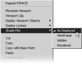
-
Take a moment to study the menu and then click As Displayed.
The As Displayed option plots the viewport as it appears in the AutoCAD window. You use this option to plot the currently displayed shaded view. Wireframe plots the viewport as a wire- frame view. Hidden plots the viewport as a hidden-line view similar to the view you see when you use the Hide command. The Rendered option plots the view by using AutoCAD's Render feature described in Chapter 17. You can use the Rendered option to plot ray-traced renderings of your 3D models.
Remember these options on the shortcut menu as you work on your drawings and when you plot. They can be helpful in communicating your ideas, but they can also get lost in the array of tools that AutoCAD offers.
Adding Dimensions and Notes in Paper Space
Although I don't recommend adding dimensions in Paper Space for architectural drawings, it might be a good idea for mechanical drawings such as the one in this chapter. By maintaining the dimensions and notes separate from the actual model, you keep these elements from getting in the way of your work on the solid model. You also avoid the confusion of having to scale the text and dimension features properly to ensure that they will plot at the correct size .
| Tip | See Chapters 8 and 9 for a more detailed discussion of notes and dimensions. |
As long as you set up your Paper Space work area to be equivalent to the final plot size, you can set dimension and text to the sizes you want at plot time. If you want text ¼ ² high, you set your text styles to be ¼ ² high.
To include dimensions, just make sure you are in a Layout tab, and then use the dimension commands in the normal way. However, you need to be careful to make sure that full associative dimensioning is turned on. Choose Tools Options to open the Options dialog box, and then click the User Preferences tab. In the Associative Dimensioning group, click the Associate New Dimensions With Objects option. With associative dimensioning turned on, dimensions in a Layout tab display the true dimension of the object being dimensioned, regardless of the image scale in the viewport.
If you do not have the associative dimensioning option turned on and your viewports are set to a scale other than 1 to 1, you have another option. You can set the Annotation Units option in the Dimension Style dialog box to a proper value. The following steps show you how:
-
Select the Model tab at the bottom of the AutoCAD window, and then choose Dimension Style to open the Dimension Style Manager dialog box.
-
Make sure you have selected the style you want to use, and then click Modify to open the Modify Dimension Style dialog box.
-
Click the Primary Units tab.
-
In the Scale Factor input box in the Measurement Scale group, enter the value by which you want your Paper Space dimensions multiplied. For example, if your Paper Space views are scaled at one-half the actual size of your model, enter 2 in this box to multiply your dimensions' values by 2.
Tip To make sure the value you need in step 4 is correct, determine which scale factor you need for your Paper Space drawing to get its actual size; that's the value you need to enter.
-
Click the Apply To Layout Dimensions Only check box. This ensures that your dimension is scaled only while you are adding dimensions in Paper Space. Dimensions added in Model Space are not affected.
-
Click OK to close the Modify Dimension Style dialog box; then click OK again in the Dimension Style Manager dialog box.
You've had to complete a lot of steps to get the final drawing, but, compared with having to draw these views by hand, you undoubtedly saved a great deal of time. In addition, as you will see later in this chapter, what you have is more than just a 2D drafted image. With what you created, further refinements are now quite easy.
Drawing a Cross-Section
One element of your drawing that is missing is a cross-section. AutoCAD will draw a cross-section through any part of the solid model. In the following exercise, you will draw such a cross-section:
-
Save your drawing so you can return to this stage (in case you don't want to save the results of the following steps).
-
Choose Tools New UCS World.
-
 Click the Section tool on the Solids toolbar.
 -
At the Select objects: prompt, click both halves of the solid model and press
. -
At the prompt
Specify first point on Section plane by [Object/Zaxis/View/XY/YZ/XZ/3points] <3points>
enter Z
X . This tells AutoCAD you want to cut the solid in the plane defined by the xand z-axes. -
At the Point on ZX plane: prompt, pick the midpoint of the top-right surface of the solid (see the first image in Figure 18.47). The section cut appears, as shown in the second image in Figure 18.47.
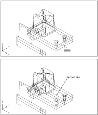
Figure 18.47: Selecting the point on the z-x plane to define the section- cut outline
The section shown in the bottom image in Figure 18.48, later in this chapter, is a type of object called a region. Next you'll learn how regions share some characteristics with 3D solids.
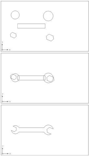
Figure 18.48: Working with regions in the Region.dwg file
Using 3D Solid Operations on 2D Drawings
You can apply some of the features described in this chapter to 2D drafting by taking advantage of AutoCAD's region object. Regions are two-dimensional objects to which you can apply Boolean operations.
Try the following optional exercise, which demonstrates how two Boolean operations, Union and Subtract, work on 2D objects.
-
If you have been working through the tutorial on 3D solids, save the Bracket drawing now.
-
On the CD Open Region.dwg supplied on the companion CD. You will see this drawing shown in the first image in Figure 18.48. The objects in this drawing are circles and closed polylines.
-
 Click the Region tool on the Draw toolbar or type Reg .
 -
At the Select objects: prompt, click all the objects in the drawing and press
. AutoCAD converts the objects into regions. -
Move the two circles and the hexagons into the positions illustrated in the second image in Figure 18.48. (For this demonstration exercise, you don't have to worry about matching the positions exactly.)
-
Choose Modify Solids Editing Union, or if you are using LT, choose Modify Region Union.
-
At the Select objects: prompt, click the rectangle and the two circles. The circles merge with the rectangle to form one object.
-
Choose Modify Solids Editing Subtract (LT users should choose Modify Region Subtract), and then click the newly created region and press .
-
At the next Select objects: prompt, click the two hexagons. Now you have a single, 2D solid object in the shape of a wrench, as shown in the final image in Figure 18.48.
You can use regions to generate complex surfaces that might include holes or unusual bends (see Figure 18.49). Keep in mind the following:
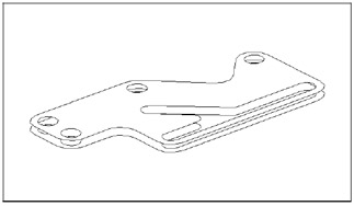
Figure 18.49: You can use the regional model to create complex 2D surfaces for use in 3D surface modeling.
-
Regions act like surfaces; when you remove hidden lines, objects behind the regions are hidden.
-
You can explode regions to edit them. (You can't do this with solids.) However, exploding a region causes the region to lose its surfacelike quality, and objects will no longer hide behind its surface(s).
EAN: 2147483647
Pages: 261