Creating Effects with Lighting
Up to now, you've used only one light source, called Distant Light, to create a sun. You have two other light sources available to help simulate light: point-light sources and spotlights . This section will show you some examples of how to use these types of light sources, along with some imagination , to perform any number of visual tricks.
Simulating the Interior Lighting of an Office Building
Our current rendering shows a lifeless-looking office building. It's missing a sense of activity. You might notice that when you look at glass office buildings , you can frequently see the ceiling lights from the exterior of the building ”provided the glass isn't too dark. In a subtle way, those lights lend a sense of life to a building.
To help improve the image, you'll add some ceiling lights to the office building. You've already supplied the lights in the form of square 3D Faces arrayed just at the ceiling level of each floor, as shown in Figure 17.11. In this section, you will learn how to make the ceiling lights appear illuminated.
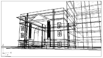
Figure 17.11: The 3D Face squares representing ceiling light fixtures
Follow these steps to assign a reflective, white material to the ceiling fixtures:
-
Assign a reflective material to the squares. Choose View Render Materials and then click the Materials Library button to open the Materials Library dialog box.
-
Locate and select White Plastic from the list on the right, and then click Import.
-
Click OK to exit the Materials Library dialog box. Then in the Materials dialog box, highlight White Plastic in the list to the left and click the By Layer button to open the Attach By Layer dialog box.
-
Make sure White Plastic is highlighted in the Select A Material list on the left; then click the Clglite layer in the Select Layer list to the right.
-
Click the Attach button. The words White Plastic appear next to the Clglite layer name in the Select Layer list.
-
Click OK to exit the Attach By Layer dialog box, and then click OK to exit the Materials dialog box.
You now have a reflective, white material assigned to the ceiling fixtures. But the reflective material alone will not give the effect of illuminated lights. You need a light source that can be reflected by the fixtures, giving the impression of illumination . For this, you'll use a point-light source:
-
Choose View 3D Views SE Isometric to get an Isometric view of the model.
-
Zoom in to the base of the office building so your view is similar to Figure 17.12.
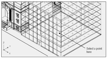
Figure 17.12: Selecting the point-light source location in the SW Isometric view -
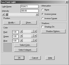
Choose View Render Light to open the Lights dialog box. Select Point Light from the New drop-down list; then click the New button to open the New Point Light dialog box.
-
Enter Point1 for the light name. Then enter 300 in the Intensity input box.
-
Click the Modify button, and then select a point at the very center of the office building base, as shown in Figure 17.12.
-
Click OK to exit the New Point Light dialog box, and then click OK in the Lights dialog box.
-
Choose View Named Views to open the Named Views dialog box. Select 3DFront and click the Set Current button.
-
Click OK to exit the Named Views dialog box.
-
Go ahead and render the view. After a minute, you will have a rendered view similar to Figure 17.13.
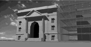
Figure 17.13: The rendered view with ceiling lights
The new point light in conjunction with the 3D Face light fixture adds a sense of life and depth to the office building. Notice that even though the light is located inside the box representing the office core, it manages to strike all the lights of all the floors as if the floors and core were transparent. Because you didn't turn on the Shadow feature for the point-light source, its light passes through all the objects in the model.
Light is even falling on the granite facade building, illuminating the inside of the arched entrance . This shows that with careful use of lighting, you can bring out some of the detail in the Facade model that might otherwise get lost with the distant light source.
Of course, you can use point-light sources in a more traditional way, representing lightbulbs or other nondirectional light sources. But by playing with light source location and shadow, you can create effects to enhance your rendering.
Simulating a Night Scene with Spotlights
Spotlights are lights that are directed. They are frequently used to provide emphasis and are usually used for interior views or product presentations. In this exercise, you'll set up a night view of the Facade model by using spotlights to illuminate the facade.
You'll start by setting up a view to help place the spotlights. After they are placed, you'll make some adjustments to them to get a view you want. Follow these steps:
-
Choose View 3D Views SE Isometric; then zoom in to the facade so your view looks similar to Figure 17.14.
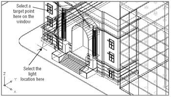
Figure 17.14: Selecting the points for the first spotlight -
Choose View Render Light to open the Lights dialog box. Select Spotlight from the New drop-down list.
-
Click New to open the New Spotlight dialog box. Enter Spot-L to designate a spotlight you will place on the left side of the facade.
-
Enter 400 in the Intensity input box. Then click the Modify button.
-
At the Enter light target <current>: prompt, use the Nearest Osnap, and select the point on the window, as indicated in Figure 17.14.
-
At the Enter light location <current>: prompt, select the point indicated in Figure 17.14. After you've selected the light location, you return to the New Spotlight dialog box. You can, in the future, adjust the light location if you choose.
-
Click OK. Then, in the Lights dialog box, click New again to create another spotlight.
-
This time, enter Spot-R for the name. Enter 400 for the intensity as before.
-
Click the Modify button and select the target and light locations indicated in Figure 17.15.
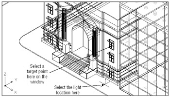
Figure 17.15: Selecting the points for the second spotlight -
Click OK to exit the New Spotlight dialog box, and then click OK again in the Lights dialog box. You now have two spotlights on your building.
-
Choose View Named Views and restore the 3DFront view.
-
Render the model. (You know how to do this by now.) Your view will look similar to Figure 17.16.
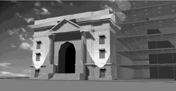
Figure 17.16: The rendered view of the model with the spotlights
The rendered view has a few problems. First, the sunlight source needs to be turned off. Second, the spotlights are too harsh . Third, you can see that the spotlights don't illuminate the center of the building, so you'll need to add some lighting at the entrance. You will solve these problems in the next section.
Controlling Lights with Scenes
The first problem is how to turn off the sun. You can set the sunlight intensity value to 0 by using the Modify Distant Light dialog box. Another way is to set up a scene. AutoCAD lets you combine different lights and views into named scenes. You can then quickly select these scenes at render time so you don't have to adjust lighting or views every time you want a specific setup.
Here's how it works:
-
 Choose View Render Scenes or click the Scenes tool on the Render toolbar to open the Scenes dialog box.
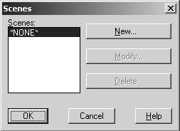
-
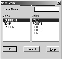
Click New to open the New Scene dialog box.
-
Enter Night in the Scene Name input box.
-
Select 3DFront from the Views list, and then Shift+click Spot-L, Spot-R, and Point1 in the Lights list.
-
Click OK. Notice that now you have Night listed in the Scenes list in the Scenes dialog box.
-
Click New again and then type Day .
-
Select 3DFront from the Views list, and Sun and Point1 from the Lights list. Then click OK. You now have two scenes set up.
-
Click OK and then open the Render dialog box. Notice that you now have Day and Night listed in the Scene To Render list box.
-
Select Night and then click the Render button. Your view will look like Figure 17.17.
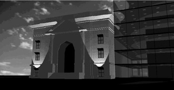
Figure 17.17: Rendering the night scene
Notice that without the sunlight source, your view is considerably darker . You will now add a few more light sources and adjust some existing ones:
-
Choose View 3D Views SE Isometric, and then zoom in to the office building so your view looks similar to Figure 17.18.
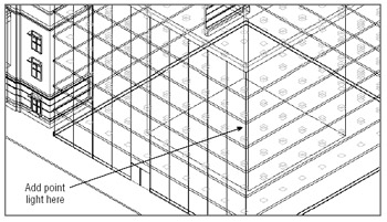
Figure 17.18: Adding another point-light source to the office building -
Open the Lights dialog box, select Point Light from the New drop-down list, and click New.
-
Enter the name Point2 and then give this new point light an intensity value of 500 .
-
Click the Modify button, and place the Point2 light in the center of the office building in the same location as Point1.
-
Click OK; then create another point-light source and enter the name Point3. Enter an intensity of 150 .
-
Click the Modify button, adjust your view so it looks similar to Figure 17.19, and then place the light in the facade entrance. Use the .X, .Y, and .Z point filters to select the location of the light, as shown in Figure 17.19.
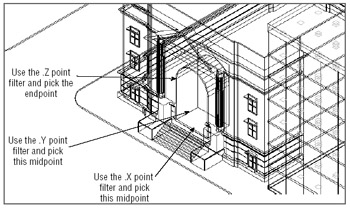
Figure 17.19: Adding a point-light source for the entrance to the facade -
Click OK. Then, in the Lights dialog box, select Spot-L from the Lights list and click Modify.
-
In the Modify Spotlight dialog box, change the Falloff value in the upper right to 80 .
-
Click OK and then repeat steps 7 and 8 for the Spot-R spotlight.
-
Click OK in the Modify Spotlight dialog box.
-
In the Lights dialog box, increase the ambient light intensity to 0.50 and then click OK.
You have installed the new lights and adjusted the spotlights. Before you render your scene, you need to include the new lights in the scene you set up for the night rendering:
-
Choose View Render Scene.
-
Highlight Night in the Scenes list and then click the Modify button.
-
Shift+click Point2 and Point3 in the Lights list, and then Ctrl+click Point1 to deselect it.
-
Click OK in both the Modify Scene and Scenes dialog boxes.
-
Choose Render and make sure Night is selected in the Scene To Render list.
-
Click the Render button. Your view will look similar to Figure 17.20.
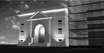
Figure 17.20: The night rendering with added lights and an increased falloff area for the spotlights
The new rendering is brighter. You can also see the effects of an increased falloff for the spotlights. They don't have the sharp edge they had in the first night rendering, and the light is spread in a wider radius, illuminating more of the lower portion of the facade.
You also see another by-product of using the Scenes tool. You didn't have to return to the 3DFront view to render the model. Because the 3DFront view is included in the scene information, AutoCAD automatically rendered the model from that view when the Night scene was selected. If you were to issue the Regen command now, you would see that AutoCAD still maintains the SE Isometric view.
EAN: 2147483647
Pages: 261