Adding Reflections and Detail with Ray Tracing
You've been gradually building up the detail and realism in your renderings by adding light and materials. In this section, you'll learn how using a different rendering method can further enhance your 3D models.
Until now, you've been using the standard AutoCAD rendering method. An alternative technique called ray tracing can add interest to a rendering, especially if reflective surfaces are prominent in a model. To make a long, complicated story short, ray tracing simulates the way light works ”in reverse. Ray tracing analyzes the light path to each pixel of your display, tracing the light, or "ray," from the pixel to the light origin as it bounces off objects in your model. In this section, you'll use the ray tracing method to render your model after making a few adjustments to the glass material.
Assigning a Mirror Attribute to Glass
Glass is a complex material to model in computer renderings. The AutoCAD standard rendering method simply gives glass a transparency with some "highlight" reflection. But glass has both refractive and reflective attributes that make it difficult to model. Because ray tracing models the way light works, it is especially well suited to rendering views that contain large areas of glass.
To demonstrate what ray tracing can do, you'll use it to render the Facade model that happens to contain an office building with a typical glass exterior. You'll start by making an adjustment to the glass material to make it appear more reflective:
-
Choose View Render Materials, and then, in the Materials dialog box, highlight Glass in the list box and click the Modify button to open the Modify Standard Material dialog box.
-
Click the Reflection radio button in the Attributes group to select it.
-
Click the Mirror check box in the Color group to select it, and then click OK to close the Modify Standard Material dialog box.
-
Click OK again in the Materials dialog box and then open the Render dialog box.
-
Choose Photo Raytrace from the Rendering Type list box.
-
Click the More Options button to open the Photo Raytrace Render Options dialog box.
-
Set the Minimum Bias setting to 0.1 and the Maximum Bias setting to 0.2. Whenever you change the rendering type, you must reset these settings. AutoCAD does not automatically transfer these settings to different rendering types.
-
Click OK and then select Day from the Scene To Render list. Click the Background button to open the Background dialog box.
-
Make sure the Use Background check box is selected in the Environment group; then click OK. This tells AutoCAD to reflect the background image in the glass.
-
Click the Render button. Your view will look similar to Figure 17.21.
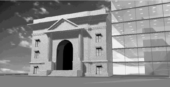
Figure 17.21: The Facade model rendered with the ray tracing method
The sky bitmap used as a background is faintly reflected in the glass of the office building. The office building has also become brighter from the reflection. Also notice the secondary reflection of the interior ceiling on the west interior wall of the office.
The brightness of the office building is a bit overwhelming, so you will want to adjust the glass material to tone it down:
-
Choose View Render Materials. Then with the Glass material highlighted, click Modify to open the Modify Standard Material dialog box.
-
Make sure the Color/Pattern radio button is selected. Then set the Value setting above the Color button group to 0.20 . This helps darken the office building.
-
Click OK to close the Modify Standard Material dialog box, and then click OK in the Materials dialog box.
-
Render the scene again. Your view will look something like Figure 17.22.

Figure 17.22: The rendering with a lower Color/Pattern setting for the Glass material
You can further reduce the brightness of the office building by reducing the intensity value of the point-light source you added earlier in this chapter.
Getting a Sharp, Accurate Shadow with Ray Tracing
In the beginning of this chapter, you learned how to use the Shadow Map method for casting shadows. Using shadow maps gives you a soft-edge shadow in exchange for accuracy. For exterior views, you might prefer a sharper shadow. The Facade example loses some detail when you use the Shadow Map method; in particular, the grooves in the base of the building disappear.
By switching to the ray tracing method for casting shadows, you can recover some of this detail:
-
Choose View Render Light. Then from the Lights list, select Sun and click Modify.
-
In the Modify Distant Light dialog box, click the Shadow Options button.
-
In the Shadow Options dialog box, click the Shadow Volumes/Ray Traced Shadows check box to select it.
-
Click OK in all the dialog boxes to exit them and return to the AutoCAD view.
-
Render the view by using the Photo Ray Trace rendering type. Your view will look like Figure 17.23.
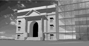
Figure 17.23: The Facade model using the Shadow Volumes/Ray Traced Shadows option
Notice that you can now see the rusticated base clearly. The shadows also appear sharper, especially around the surface detail of the Facade model.
EAN: 2147483647
Pages: 261