Using the Layout Tabs and Paper Space
Your set of drawings for this studio apartment building would probably include a larger-scale, more detailed drawing of the typical unit plan. You already have the beginnings of this drawing in the form of the Unit file.
As you have seen, the notes and dimensions you entered into the Unit file can be turned off or frozen in the Plan file so they don't interfere with the graphics of the drawing. The Unit file can be part of another drawing file that contains more detailed information on the typical unit plan at a larger scale. To this new drawing you can add other notes, symbols, and dimensions. Whenever the
Unit file is altered , you update its occurrence in the large-scale drawing of the typical unit as well as in the Plan file (see Figure 12.31). The units are thus quickly updated, and good correspondence is ensured among all the drawings for your project.
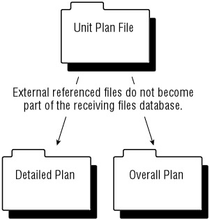
Figure 12.31: The relationship of drawing files in a project
Now suppose that you want to combine drawings having different scales in the same drawing file ”for example, the overall plan of one floor plus an enlarged view of one typical unit. You can do so using the Layout tabs and a feature called Paper Space.
Understanding Model Space and Paper Space
So far, you've looked at ways to help you get around in your drawing while using a single view. This single view representation of your AutoCAD drawing is called the Model Space display mode. You can also set up multiple views of your drawing, called floating viewports. You create floating viewports by using the Layout tabs to work in Paper Space display mode.
To get a clear understanding of the Model Space and Paper Space modes, imagine that your drawing is actually a full- size replica or model of the object you are drawing. Your computer screen is your window into a "room" where this model is being constructed , and the keyboard and mouse are your means of access to this room. You can control your window's position in relation to the object through the use of Pan, Zoom, View, and other display- related commands. You can also construct or modify the model by using drawing and editing commands. Think of this room as your Model Space.
So far, you have been working on your drawings by looking through a single "window" into Model Space. Now suppose you have the ability to step back and add windows with different views looking into your Model Space. The effect is as if you have several video cameras in your Model Space "room," each connected to a different monitor. You can view all your windows at once on your computer screen or enlarge a single window to fill the entire screen. Further, you can control the shape of your windows and easily switch from one window to another. This is what Paper Space is like.
Paper Space lets you create and display multiple views of Model Space. Each view window, called a viewport, acts like an individual virtual screen. One viewport can have an overall view of your drawing, while another can be a close-up. You can also control layer visibility individually for each viewport and display different versions of the same area of your drawing. You can move, copy, and stretch viewports and even overlap them.
| Tip | Another type of viewport, called the Tiled viewport, can be set up in Model Space. Chapter 16 discusses this type of viewport. |
Perhaps one of the more powerful features of Paper Space is that you can plot several views of the same drawing on one sheet of paper. You can also include graphic objects such as borders and notes that appear only in Paper Space. In this function, Paper Space acts much like a page-layout program such as QuarkXPress or Adobe PageMaker. You can "paste up" different views of your drawing and then add borders, title blocks, general notes, and other types of graphic and textural data. Figure 12.32 shows the Plan drawing set up in Paper Space mode to display several views.
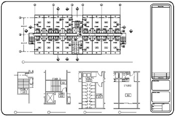
Figure 12.32: Different views of the same drawing in Paper Space
Creating a Paper Space Layout
Your gateway to Paper Space is the Layout tab at the bottom of the AutoCAD window. When the Model tab is selected, you are in Model Space. When you select a Layout tab, you are in Paper Space.
| Tip | You can also use a system variable to switch between tabs. When Tilemode is set to 1 (On), the default setting, you are in Model Space. When it is set to 0 (Off), you are in Paper Space. |
Let's start with the basics of entering Paper Space:
-
If it isn't already open, open the Xref-1 file, making sure your display shows all of the drawing.
-
Click the Layout1 tab or click Model on the status bar, then right click the Layout1 tab and select Page Setup Manager.
-
At the Page Setup Manager dialog box, click the Modify button to open the Page Setup dialog box.
-
Select the Letter paper size option from the Paper Size drop-down list. Metric users should select A4 (210 mm 297 mm). The paper size you select here determines the shape and margin of the Paper Space layout area.
-
Click OK. Note that the word PAPER replaces the word MODEL in the status bar; this tells you at a glance that you are in Paper Space.
AutoCAD bases the Paper Space work area on the paper size that you specify. The area shown in Paper Space reflects the area of the paper size you select in step 4. If for some reason you need to change the paper size, you can do so by repeating steps 2 through 5. You can also store the way you've set up your paper space layout using the Page Setup Manager you saw in step 2. See "Storing a Page Setup" in Chapter 7 for more on this feature.
Creating New Paper Space Viewports
As you saw in Chapter 7, the different look of the Layout tab tells you that you are in Paper Space. You also learned that a viewport is automatically created when you first open a Layout tab . The viewport displays an overall view of your drawing to no particular scale.
In this section, you will work with multiple viewports in Paper Space, instead of just the default single viewport you get when you open the Layout tab.
This first exercise shows you how to create three new viewports at once:
-
Right-click the Draw or Modify toolbar, and choose Viewports to open the Viewports tool- bar. You'll use this toolbar a bit later in this exercise.
-
Click the viewport border to select it. The viewport border is the solid rectangle surrounding your drawing, just inside the dashed rectangle.
-
 Click the Erase tool to erase the viewport. Your drawing disappears. Don't panic; remember that the viewport is like a window to Model Space. The objects in Model Space are still there.
 -
Click Display Viewports Dialog in the Viewports toolbar to open the Viewports dialog box. You can also choose View Viewports New Viewports. This dialog box contains a set of predefined viewport layouts.

Tip You'll learn more about the Viewports dialog box and its options in Chapter 16.
-
Click the Three: Above option in the Standard Viewports list box. The box to the right shows a sample view of the Three: Above layout you selected.
-
Click OK. The Specify first corner or [Fit] <Fit>: prompt appears.
-
Press
 to accept the default Fit option. The Fit option fits the viewport layout to the maximum area allowed in your Paper Space view. Three rectangles appear in the formation, as shown in Figure 12.33. Each of these is a viewport to your Model Space. The viewport at the top fills the whole width of the drawing area; the bottom half of the screen is divided into two viewports.
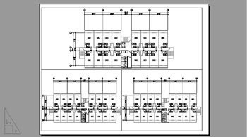
Figure 12.33: The newly created viewports
When you create new viewports, AutoCAD automatically fills the viewport with the extents of your Model Space drawing. You can specify an exact scale for each viewport, as you'll see later.
Notice that the dashed line representing your paper margin has disappeared. That's because the viewports are pushed to the margin limits, thereby covering the dashed line.
You could have kept the original viewport that appeared when you first opened the Layout1 tab and then added two new viewports. Completely replacing the single viewport is a bit simpler because the Viewports dialog box fits the viewports in the allowed space for you.
Reaching Inside Viewports
Now suppose you need access to the objects within the viewports in order to adjust their display and edit your drawing. Try these steps:
-
Click Paper on the status bar. This gives you control over Model Space even though you are in Paper Space. (You can also enter MS
as a keyboard shortcut to entering Model Space mode.) The first thing you notice is that the UCS icon changes back to its L-shaped arrow form. It also appears in each viewport, as if you had three AutoCAD windows instead of just one.
-
Move your cursor over each viewport. Notice that in one of the viewports the cursor appears as the AutoCAD crosshair cursor, while in the other viewports it appears as an arrow pointer. The viewport that shows the AutoCAD cursor is the active one; you can pan and zoom, as well as edit objects in the active viewport.
Tip If your drawing disappears from a viewport, you can usually retrieve it by choosing View Zoom Extents ( Zoom
E ). -
Click the lower-left viewport to activate it.
-
Choose View Zoom Window and place a selection window the elevator area.
-
Click the lower-right viewport and choose View Zoom Window to enlarge your view of a typical unit. You can also use the Pan Realtime and Zoom Realtime tools.
Tip If you don't see the UCS icon, it has been turned off. Type UCSicon
On to turn it on. See Chapter 16 for more on the UCS icon.
When you click the Paper button on the status bar, the UCS icon again changes shape ”instead of one triangular -shaped icon, you have three arrow-shaped ones, one for each viewport on the screen. Also, as you move your cursor into the currently active viewport, the cursor changes from an arrow into the usual crosshair. Another way to tell which viewport is the active one is by its bold border.
| Tip | You can also switch between Model Space and Paper Space by double-clicking an area in either region. For example, to go to Model Space from Paper Space, double-click inside a viewport. To get back to Paper Space, double-click the area outside the viewport. If you have an enlarged view of a viewport and no portion of the Paper Space area is available to click, click the Paper button on the status bar. |
You can move from viewport to viewport even while you are in the middle of most commands. For example, you can issue the Line command, pick the start point in one viewport, go to a different viewport to pick the next point, and so on. To activate a different viewport, you simply click it (see Figure 12.34).
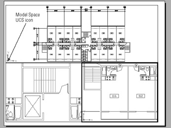
Figure 12.34: The three viewports, each with a different view of the plan
| Tip | You might find it difficult to access the contents of overlapping viewports, especially if the viewports are the same size or if one is enclosed by another. In this situation, you can move between viewports by pressing Ctrl+R repeatedly until you get to the viewport you want. |
You've seen how you can zoom into a viewport view, but what happens when you use the Zoom command while in Paper Space? Try the following exercise to find out:
-
Click the Model button on the status bar or double-click an area outside the viewports to return to Paper Space.
-
 Click the Zoom Realtime tool in the Standard toolbar and then zoom in to the Paper Space view. The entire view enlarges, including the views in the viewports.
 -
Choose View Zoom All or enter Z
A to return to the overall view of Paper Space.
This brief exercise shows that you can use the Zoom tool in Paper Space just as you would in Model Space. All the display-related commands are available, including the Pan Realtime command.
Getting Back to Full-Screen Model Space
After you've created viewports, you can then reenter Model Space through the viewport by using the Model/Paper button on the status bar. This button performs two functions: it shows you which space you are in, and it enables you to switch between the two spaces. But what if you want to quickly get back into the old, familiar, full-screen Model Space you were in before you entered Paper Space?
The following exercise demonstrates how this is done:
-
Click the Model tab at the bottom of the drawing area or enter Tm
1 . Your drawing returns to the original full-screen Model Space view ”everything is back to normal. -
Click the Layout1 tab or enter Tm
. You are back in Paper Space. Notice that all the viewports are still there when you return to Paper Space. After you've set up Paper Space, it remains part of the drawing until you delete all the viewports. Also notice that you didn't see the Page Setup dialog box this time. After you've chosen a sheet size, AutoCAD assumes that you will continue to use that sheet size and other page setup information until you tell it otherwise .
You might prefer using Model Space for doing most of your drawing and using Paper Space for setting up views for plotting. Because viewport layouts are retained, you won't lose anything when you go back to Model Space to edit your drawing.
EAN: 2147483647
Pages: 261