Working with Paper Space Viewports
Paper Space is intended as a page-layout or composition tool. You can manipulate viewports' sizes, scale their views independently of one another, and even set layering and line-type scales independently.
Let's try manipulating the shape and location of viewports by using the Modify toolbar options:
-
Turn off Running Osnaps if it is on.
-
Make sure you're in Paper Space (the Paper button should appear to the right of the status bar buttons ). Then click the bottom edge of the lower-left viewport to expose its grips (see the top image in Figure 12.35).
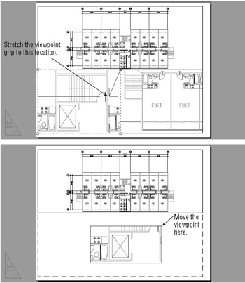
Figure 12.35: Stretching, erasing, and moving viewports -
Click the upper-right grip and then drag it to the location shown in the top image in Figure 12.35.
-
Press the Esc key and then erase the lower-right viewport by clicking Erase in the Modify toolbar. Then click the bottom edge of the viewport.
-
Move the lower-left viewport so it is centered in the bottom half of the window, as shown in the bottom image in Figure 12.35.
In this exercise, you clicked the viewport edge to select it for editing. If, while in Paper Space, you attempt to click the image within the viewport, you will not select anything. Later you will see, however, that you can use the Osnap modes to snap to parts of the drawing image within a viewport.
Because viewports are recognized as AutoCAD objects, you can manipulate them by using all the editing commands, just as you would manipulate any other object. In the previous exercise, you moved, stretched , and erased viewports.
Next , you'll see how layers affect viewports:
-
Create a new layer called Vport .
-
In the Properties palette, change the viewport borders to the Vport layer.
-
Finally, turn off the Vport layer. The viewport borders disappear.
-
After reviewing the results of step 3, turn the Vport layer back on.
You can assign a viewport's border a layer, a color , a line type, and even a line weight. If you put the viewport's border on a layer that has been turned off or frozen, that border becomes invisible, just like any other object on such a layer. Making the borders invisible is helpful when you want to compose a final sheet for plotting. Even when turned off, the active viewport has a heavy border around it when you switch to the floating model, and all the viewports still display their views.
| |
As you add more viewports to a drawing, some of them might blank out even though you know you haven't turned them off. Don't panic. AutoCAD limits the number of viewports that display their contents at any given time to 64. (A viewport that displays its contents is said to be active. ) This limit is provided because too many active viewports can bog down a system.
If you are using a slow computer with limited resources, you can lower this limit to two or three viewports to gain some performance. Then only two or three viewports will display their contents. (All viewports that are turned on will still plot, regardless of whether their contents are visible.) Zooming in to a blank view- port restores its visibility, thereby enabling you to continue to work with enlarged Paper Space views containing only a few viewports.
The Maxactvp system variable controls this value. Type Maxactvp and then enter the number of view- ports you want active at any given time.
| |
Scaling Views in Paper Space
Paper Space has its own unit of measure. You have already seen how you are required to specify a paper size when opening a Layout tab to a Paper Space view. When you first enter Paper Space, regardless of the area your drawing occupies in Model Space, you are given limits that are set by the paper size you specify in the Page Setup dialog box. If you keep in mind that Paper Space is like a paste-up area that is dependent on the printer you configured for AutoCAD, this difference of scale becomes easier to comprehend. Just as you might paste up photographs and maps representing several square miles onto an 11 ² 17 ² board, so can you use Paper Space to paste up views of scale drawings representing city blocks or houses on an 8 ½ ² 11 ² sheet of paper. But in AutoCAD, you have the freedom to change the scale and size of the objects you are pasting up.
| Tip | While in Paper Space, you can edit objects in a Model Space viewport, but to do so, you must use Floating Model Space. You can then click a viewport and edit within that viewport. While in this mode, objects that were created in Paper Space cannot be edited. Choosing View Paper Space brings you back to the Paper Space environment. |
If you want to be able to print your drawing at a specific scale, you must carefully consider scale factors when composing your Paper Space paste-up. Let's see how to put together a sheet in Paper Space and still maintain accuracy of scale:
-
Make sure you're in Paper Space. Check to see whether the Paper button appears on the status bar. If Model appears there, click that button to change it to Paper.
-
Click the topmost viewport's border to select it.
-
Right-click and then choose Properties from the shortcut menu to open the Properties palette.
-
Scroll down the list of properties until you see the Standard Scale listing.
-
Click the Custom setting next to the Standard Scale listing; then click the downward-pointing arrow that appears next to Custom to open the list.
-
Select 1 / 32 ² = 1 ¢ from the drop-down list. Notice how the view in the top viewport changes.
-
Press the Esc key twice to clear the selection of the viewport.
-
Click the lower viewport border. The information in the Properties palette changes to reflect the properties of the newly selected viewport.
-
Click the Standard Scale Custom listing and open the drop-down list as you did in step 5.
-
Select 3 / 16 ² = 1 ¢ from the list. Notice that the view in the viewport changes to reflect the new scale (see Figure 12.36).
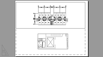
Figure 12.36: Paper Space view- port views scaled to 1 / 32 ² = 1 ¢ and 3 / 16 ² = 1 ¢
It's easy to adjust the width, height, and location of the viewports so that they display only the parts of the unit you want to see. While in Paper Space, use the Stretch, Move, or Scale command to edit any viewport border, or just use the viewport's grips to edit its size. The view within the view- port itself remains at the same scale and location, while the viewport changes in size. You can move and stretch viewports with no effect on the size and location of the objects within the view.
If you need to overlay one drawing on top of another, you can overlap viewports. Use the Osnap overrides to select geometry within each viewport, even while in Paper Space. This enables you to align one viewport on top of another at exact locations.
You can also add a title block in Paper Space at a 1:1 scale to frame your viewports and then plot this drawing from Paper Space at a scale of 1:1. Your plot appears just as it does in Paper Space, at the appropriate scale. Paper Space displays a dashed line to show you where the nonprintable areas occur near the edge of the paper.
While working in Paper Space, pay close attention to whether you are in Paper Space or Floating Model Space mode. It is easy to accidentally perform a pan or zoom within a Floating Model Space viewport when you intend to pan or zoom your Paper Space view. This can cause you to lose your view- port scaling or alignment with other parts of the drawing. It's a good idea to save viewport views by choosing View Named Views in case you happen to accidentally change a viewport view.
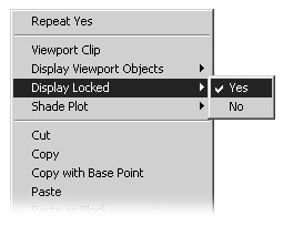
Another way to prevent your viewport view from being accidentally altered is to turn on View Lock. To do this, while in Paper Space, click a viewport border. Right-click to open the shortcut menu, and then choose Display Locked Yes. After the view is locked, you cannot pan or zoom a viewport view. You also cannot change the size of the viewport. This setting is also available in the viewport's Properties palette.
| Tip | If your viewport views are automatically zooming to extents when you enter them, the Ucsfollow system variable has been changed from its default setting of 0 (zero). Change Ucsfollow back to 0 by typing Ucsfollow |
Setting Layers in Individual Viewports
Another unique feature of Paper Space viewports is their ability to freeze layers independently. You could, for example, display the usual plan information in the overall view of a floor but show only the walls in the enlarged view of one unit.
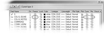
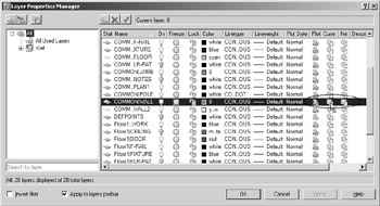
You control viewport layer visibility through the Layer Properties Manager dialog box. You might have noticed that there are three sun icons for each layer listing.
| Tip | You might need to widen the Layer Properties Manager dialog box to view all the columns . Simply click and drag the right border of the dialog box to the right. |
You're already familiar with the sun icon farthest to the left. This is the Freeze/Thaw icon that controls the freezing and thawing of layers globally. Several columns to the right of that icon is a sun icon with a transparent rectangle. This icon controls the freezing and thawing of layers in individual viewports.
This exercise shows you firsthand how this icon works:
-
Click the Paper button on the status bar to go to Floating Model Space.
-
Activate the lower viewport.
-
Open the Layer Properties Manager dialog box.
-
Locate the CommonWALL layer; then click its name to help you isolate this layer.
Warning You cannot use the Cur VP and New VP options in the Layer Properties Manager dialog box while you are in model tab.
-
Click the column labeled Current VP Freeze for the selected layer. You might need to widen the Layer Properties Manager dialog box to do this. The Current VP Freeze column is the second column from the right side of the dialog box. Click the icon, which looks like a transparent rectangle over a sun. After you've clicked the icon, the sun changes to a snowflake , telling you that the layer is now frozen for the current viewport.
-
Click OK. The active viewport regenerates, with the Wall layer of the Common Xref made invisible in the current viewport. However, the walls remain visible in the other viewport (see Figure 12.37).
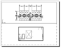
Figure 12.37: The drawing editor with the Wall layer turned off in the active viewport -
After reviewing the effects of the Current VP Freeze setting, go back to the Layer Properties Manager and thaw the CommonWALL layer by clicking its Current VP Freeze icon again so it turns back into a sun.
-
Click OK to exit the dialog box.
-
Take a moment to study the drawing, then save and exit the Xref-1 file.
You might have noticed another, similar sun icon next to the one you used in the previous exercise. This icon shows an opaque rectangle over the sun. This icon controls layer visibility in any new view- ports you might create next, rather than controlling existing viewports.
If you prefer, you can also use the Layer drop-down list in the Properties toolbar to freeze layers in individual viewports. Double click in the viewport you want to modify, select the layer from the list, and then click the same sun icon with the small rectangle below it.
| |
Chapter 6 described a method for using AutoCAD's Draw Order feature to hide floor patterns under equipment or furniture in a floor layout. You can use a similar method to hide irregularly shaped areas in a Paper Space viewport. This would be desirable for plotting site plans, civil plans, or floor plans that require portions of the drawing to be masked out. Or you might want to mask part of a plan that is overlapped by another to expose dimension or text data.
| |
This section concludes the apartment building tutorial. Although you haven't drawn the complete building, you've already learned all the commands and techniques you need to do so. Figure 12.38 shows you a completed plan of the first floor; to complete your floor plans and get some practice using AutoCAD, you might want to add the symbols shown in this figure to your Plan file.
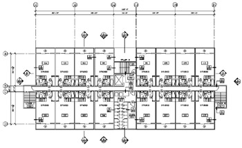
Figure 12.38: A completed floor of the apartment building
On the CD Because buildings like this one often have the same plans for several floors, the plan for the second floor can also represent the third floor. Combined with the first floor, this gives you a three-level apartment building. This project might also have a ground-level garage, which would be a separate file. You can use the Col-grid.dwg file from the companion CD in the garage file as a reference for dimensions. The other symbols can be blocks stored as files that can be retrieved in other files.
| |
The San Francisco Main Library project made extensive use of Paper Space. As you've seen in earlier chapters, the library project used multiple instances of the same file to show different types of information. Paper Space was instrumental in enabling the CAD specialists to manage large amounts of drawing data. One floor-plan drawing served as the basis for several sheets, including floor plans, reflected ceiling plans, equipment plans, exit plans, and others.
The following image shows a Paper Space view of a drawing from the San Francisco Main Library construction document set. This particular sheet shows the floor pattern layout of some of the main circulation areas.
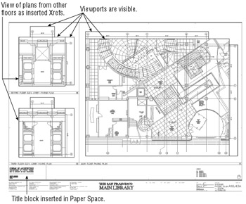
The title block is inserted in Paper Space as a block, rather than as an Xref. This was done because each drawing has unique drawing title information that is kept as attribute data in the title block. The attributes can be easily updated from a dialog box.
The plan drawings are Xrefs inserted into Model Space, with Paper Space viewports displaying selected areas. The viewport borders are turned on in this view to show how they are arranged. These borders are turned off when the drawing is plotted.
Notice that the grid reference symbols are in their own viewport adjacent to the main enlarged floor plan. These adjacent grid viewports display portions of the drawing that are actually some distance away from the floor plan shown in the main viewport. The following image shows the overall floor plan with the view- port areas outlined. Here you can see that the column grid symbols are actually at the edge of the drawing.
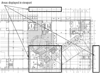
This example shows how viewports helped the creator of this drawing reuse existing data. If a change is made to the overall plan, including the column grids, the enlarged plan of the entry is automatically updated.
| |
Creating and Using Multiple Paper Space Layouts
You're not limited to just one or two Paper Space layouts. You can have as many Paper Space layouts as you want, with each layout set up for a different sheet size containing different views of your drawing. You can use this feature to set up multiple drawing sheets based on a single AutoCAD drawing file. For example, a client requires full sets of plans in both 1 / 8 ² = 1 ¢ scale and 1 / 16 ² = 1 ² scale. You can set up two Layout tabs, each with a different sheet size and viewport scale.
You can also set up different Paper Space layouts for the different types of drawings. In the San Francisco Main Library project, a single drawing contained the data for mechanical layout, equipment and furnishing , floor plans, and reflected ceiling plans. Although that project used multiple files to set the layers for each plan, a single file with multiple Layout tabs can serve the same purpose in AutoCAD 2005.
To create new Layout tabs, do the following:
-
Right-click any tab.
-
Choose New Layout from the shortcut menu to add a new tab to those that already exist.
-
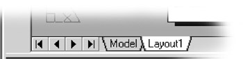
Click the new layout tab. The layout appears with a single default viewport.
In step 1, you may have noticed that the Layout tab shortcut menu includes the From Template option. The From Template option lets you create a Paper Space layout based on an AutoCAD template file. AutoCAD offers several standard layouts that include title blocks based on common sheet sizes.
The Layout tab shortcut menu also includes options that enable you to delete, rename, move, copy, or select all the tabs. If there are more tabs than can fit in the space provided, you can navigate the tabs by using the arrows just to the left of the tabs.
Creating Odd-Shaped Viewports
ACAD only In many situations, a rectangular viewport will not provide a view appropriate for what you want to accomplish. For example, you might want to isolate part of a floor plan that is L-shaped or even circular. You can create viewports from virtually any shape you need, as the following exercise demonstrates .
| Warning | This feature is not availble in AutoCAD LT. |
Follow these steps to set up the Layout tab to show only the lower apartment units and the elevators and stairs:
-
 Click the Clip Existing Viewport tool in the Viewports toolbar. You can also choose Modify Clip Viewport.
 -
At the Select viewport to clip: prompt, click the viewport border.
-
At the Select clipping object or [Polygonal] <Polygonal>: prompt, press
 .
. -
Turn off Running Osnaps and draw the outline shown in the top portion of Figure 12.39.
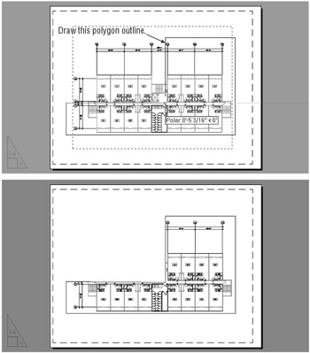
Figure 12.39: Drawing a polygon outline for a viewport -
After you finish selecting points, press
. The viewport changes to conform to the new shape. -
Click the viewport border to expose its grips.
-
Click a grip and move it to a new location. Notice that the viewport view conforms to the new shape, as shown in the bottom view of Figure 12.39.
The new viewport shape gives you more flexibility in isolating portions of a drawing. This can be especially useful if you have a large project that is divided into smaller sheets. You can set up several Layout tabs, each displaying a different portion of the plan.
What if you want a viewport that is not rectilinear? This exercise shows you how to create a circular viewport:
-
Erase the viewport you just modified.
-
Draw a circle that roughly fills the Paper Space area.
-
Click the Convert Object To Viewport option on the Viewports toolbar or choose View Viewports Object.
-
Click the circle. The plan appears inside the circle, as shown in Figure 12.40.
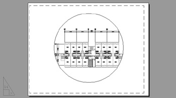
Figure 12.40: A circular viewpoint
To simplify this exercise, you were asked to draw a circle as the basis for a new viewport. However, you are not limited to circles; you can use any closed polyline or spline of any shape (see Chapter 13 for a detailed discussion of polylines and splines). You can also use the Polygon tool in the Draw toolbar to create a shape and then turn it into a viewport.
If you look carefully at the series of prompts for the previous exercise, you'll notice that the Convert Object To Viewport option invokes a command-line version of the Vports command ( “vports). This command-line version offers some options that the standard Vports command does not. The following options are available with the command-line version of Vports:
-vports [ON/OFF/Fit/Shadeplot/Lock/Object/Polygonal/Restore/2/3/4] <Fit>:
You used two of the options in the two previous exercises, the Polygonal option and the Object option. If you're an experienced AutoCAD user , you might notice that this command-line version of Vports is the same as the Mview command of earlier releases. You can still use the Mview command if you prefer.
EAN: 2147483647
Pages: 261