Flylib.com

Books Software


Sharing the Local Roadway: Ethernet Hubs


Sharing the Local Roadway: Ethernet Hubs

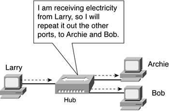
An old friend of mine is a native of San Francisco and still lives there. The traffic is horrible there, in part due to the need for lots of people to commute across the San Francisco Bay. There simply aren't enough bridges for the number of cars that need to cross the Bay. His solution: Fill in the Bay with dirt and pave the whole thing. Then there would be plenty of roads to allow people to cross the Bay.

If you tried to connect 10 PCs in a network, using a cross-over cable between NICs (as shown in figure 4-10), you would begin to do the equivalent of paving the San Francisco Bay. You know how two computers can use Ethernet NICs with a cross-over cable to communicate. However, to connect to other PCs, you would need more Ethernet NICs, and your PC probably does not have enough room for all the cards. Also, you would need to run cables between your PC and all the other PCs, or at least get the electrician to run the cables. If you tried to do this for 100 PCs on the same floor of the building, and every PC wanted to connect to every other, you would have 99 cables connected to 99 NICs inside each PC!

The alternative to running a cable to every other PC is to run a cable from each PC to a wiring closet and connect the cables to a networking device, called an Ethernet hub. An Ethernet hub provides several functions, but mainly it allows the electrician to cable each device to the hub using only a single NIC and single cable, eliminating the cabling problem. The hub simply listens for incoming electrical signals, and when received, the hub repeats the same electrical signal to every other device that's connected to the hub. Figure 4-11 shows the basic operation.

Figure 4-11. Ethernet Hub Repeats Everything It Hears


As seen in the figure, Larry sends data to the hub, and the hub repeats what Larry sent out the cables to Archie and Bob. It's that simple!

Figure 4-11 shows cabling, but it does not show which pairs of wires are used. Interestingly, the hub expects straight-though Ethernet cabling between itself and the PCs. Why is that? Well, the people who make hubs, knowing that Ethernet NICs in PCs send on the twisted pair that uses pins 1 and 2 and receive on twisted pair that uses pins 3 and 6, do the opposite . Therefore, a straight-through cable works between a PC NIC and a hub. Figure 4-12 illustrates the concept.

Figure 4-12. Hubs Use Straight-Through Cabling to PCs


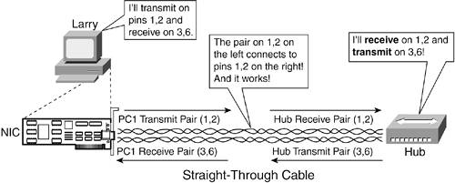
The hub's logic is simple:

1.

Receive traffic on pins 1 and 2 on each physical interface.

2.

When received, repeat the same electrical signal out all other ports, except the one in which the data was received.

3.

When repeating out other ports, repeat the traffic out pins 3 and 6 so that the PCs will be listening.


Dirt Roads Versus the DOT

You can spend a long time working around or in the networking arena and not ever need to worry about how structured cabling works. This section gives you a brief glimpse into the world of structured cabling, just so you know what people are talking about if they bring it up.

You can go to the store and buy premade Ethernet UTP cables with RJ-45 connectors on them. You can even buy a huband for not a lot of money, typically less than $20. You could then connect a bunch of computers to the hub using the straight-through Ethernet cables, and voil, you have a network, or at least the part that allows the computers to send and receive data. Running your own cabling is quick and easy.

In a real network in a real building, you will not typically get away with stringing cables on top of the carpet, over people's cubicles, and so on. Instead, you should allow the electricians to do their job right, which means that the cables will run either under the floor or inside the ceiling. Also, instead of a single cable from a PC to the hub, the equivalent will be created. First, you install a short cable from the PC to a wall plate. The electrician runs another cable from the back of the wall plate to the wiring closet into a patch panel. Finally, either the electrician or the network engineer connects a cable from the patch panel in the wiring closet to the hub. Together, these cables provide two twisted pair between the PC NIC and the hub. Figure 4-13 shows the major components .

Figure 4-13. Major Components of a Structured Wiring Plan


Structured wiring allows the electrician to take care of the difficult part of cabling, with a minimum of cost, effort, and clutter, while still making sure that the cabling works correctly. Even though multiple cables are used, the net result of the cabling simply needs to ensure that the correct twisted pairs end up at the right place in the connectors at the endpoints. And the only cables that the people in the offices can see are the short ones between the PC and the wall plate; the rest of the cables are hidden.

Imagine that if instead of structured wiring, the electrician simply ran a single cable from the computer, under the floor, and straight into the hub in the wiring closet. Later, the person in the cubicle decides that she wants her PC on the left side of her desk, and she might discover that the cable is too short. So what does she do? She calls the electrician and asks for another cable to be run.

Of course, the electrician probably isn't going to want to run a new cable from the cubicle to the wiring closet. If he had used structured wiring, he could have run a cable from the wall plate to the patch panel in the wiring closet. A patch panel , sometimes called a wiring panel , provides the electrician a place to connect the actual wires in the cable on one side of the panel. On the other side, receptacles, much like the ones in the wall plate in the cubicle, allow the electrician or network engineer to use a short cable to connect those pairs of wires to some other devices, such as the hub shown in Figure 4-13.

Because the patch panel is located in a well-known place, and because the wall plate in the cubicles does not move, the electrician can do the hard part (running the cables under the floor) once. If the PC in the cubicle needs to be moved farther away from the wall, the PC user can get a slightly longer patch cable. A patch cable is simply a short LAN cable. Likewise, inside the wiring closet, short patch cables can be used to connect from the patch panel to the networking device, such as the hub shown in Figure 4-13.

You can think of structured wiring as the equivalent of having the DOT build your roads versus just using dirt roads. It takes time, planning, effort, and more cost, but in the end, you have a much better road system. With structured wiring, you end up with much better wiring and far less clutter. Furthermore, you can make changes without a lot of effort.

The benefits of structured cabling can be summarized as follows :

  • Helps minimize the need for running new cables because the distance from each wall plate to the wiring panel can be determined easily

  • Allows PC installers to run a short patch cable from the wall plate to the PC, without requiring help from the electrician

  • Allows network engineers to run a short patch cable from the wiring panel to the networking devices, such as a hub

  • Helps keep the wiring closet more organized