IPSec Basics
|
| Even though IP has become the most-used communication protocol in the world and is the backbone technology behind the Internet, it still has many flaws. Some of these issues are address space limitations, no auto-configuration of hosts, and a lack of intrinsic security. The main reason for these flaws is that IP wasn't designed for use by the masses. It was actually designed for a much smaller, self-sufficient, contained environment. Because IP has invaded most businesses and homes, many of these flaws have been patched with other protocols and programs. In an effort to move IP forward, a new version of the protocol, IPv6 (IP version 6), was born, with built-in functionality that takes care of many of the issues of its predecessor. Because the adoption of a new version of IP in our constantly growing, current Internet environment has been difficult, the security measures incorporated into IPv6 have also been ported to our current version of IP (version 4) as an optional protocol suite. This set of protocols is known as the IPSec Protocol Suite. IPSec Protocol SuiteIPSec's goal is to facilitate the confidentiality, integrity, and authentication of information communicated using IP. This is accomplished through the use of several protocols, including Internet Key Exchange (IKE), Encapsulating Security Payload (ESP), and Authentication Header (AH). These three protocols combine to allow the secure exchange of information without fear of outside eavesdropping or tampering. A second goal of the security suite is a means for multiple vendors to have a set of standards by which they can interoperate securely. Industrywide testing is being done to verify that the products of these vendors can all work together correctly to provide sound IPSec implementations. IPSec-based security starts with the forming of a security association (SA) between two communicating parties. SAAn SA is basically an agreement between two entities on how they will securely transmit information. One of the exceptional things about IPSec is the openness of its standard to support not only multiple protocols and communication modes, but also various encryption algorithms and hash types. All these details must be prenegotiated before the secure exchange of user data can begin. The resultant agreement is an SA. Each communication session has two SAsone for each communication partner. Each partner negotiates a new SA for every IPSec connection he makes. Before an SA is negotiated, the particular settings that an IPSec partner is going to support must be configured for it locally. These settings are held in what is known as a security policy database (SPD). After the SA has been negotiated, it is contained in a security association database (SAD). This is necessary because different communication rules can be configured for each of the sessions that a host or device might initiate. For example, look at Figure 7.2. A Cisco PIX firewall can be set up to allow Data Encryption Standard (DES) or 3DES as the encryption algorithm for a VPN tunnel. When Host 1 connects, it might only support DES and would negotiate an SA with DES encryption. However, Host 2 behind another PIX might also attempt to create a tunnel with our PIX, and it might require a 3DES tunnel because of its own business and security requirements. In this case, only a 3DES tunnel could be negotiated. Each of these negotiated connections would require its own SA entry in the SAD, listing all the specific details of what was negotiated for each. These details will include such information as encryption algorithm negotiated (DES, 3DES, AES, and so on), VPN mode, security protocol negotiated (ESP or AH), and hash algorithm negotiated (MD5 or SHA-1). Figure 7.2. IPSec connection parameters negotiated for VPN tunnels are maintained in the SAD.
Because multiple IPSec sessions are available per device (each with its own set of unique settings), for this process to function correctly, each SA session must have its own singular identifier. This identifier is made up of a unique security parameter index (SPI) that tells which SA database entry pertains to the connection in question, the destination address of the connection, and the protocol identifier for the ESP or AH protocol, whichever is being used for the connection. Listing 7.1 is an excerpt from a Cisco router's SA database for an inbound ESP connection. Listing 7.1. Cisco Router SA Database inbound esp sas: spi: 0x71BB425D(1908097629) transform: esp-des esp-md5-hmac, in use settings ={Tunnel, } slot: 0, conn id: 2000, flow_id: 1, crypto map: mode sa timing: remaining key lifetime (k/sec):(4608000/3500) IV size: 8 bytes replay detection support: Y This excerpt contains much information about this specific connection, such as the SPI number of the connection, the encryption and hash algorithms being used for this connection, the fact that it is working in tunnel mode, and the lifetime for this connection. This information is recorded in the SAD for each negotiated connection. IPSec Tunnel and Transport ModesAn IPSec connection has two basic modes: transport and tunnel. Transport mode is a host-to-host form of communication and involves the encryption of a packet's payload only. Because of this host-to-host requirement, software needs to be loaded on all communicating hosts, which in large installations can be an administrative nightmare. However, this VPN mode is well-suited for encrypted communications between hosts on the same network, or in situations where it is important to be able to differentiate hosts by their IP address information. Transport mode lacks a means to do gateway-to-gateway communication and the ability to conceal host IP information, which can be a major concern when your data is traversing a public medium such as the Internet. Transport mode communication can be coupled with other tunneling means for a more secure communication channel. The other IPSec mode takes advantage of tunneling. Tunneling mode is the method of choice for most VPNs because it encrypts not only the payload but also the entire original packet, partially or completely obfuscating the source and destination addresses of the communicating systems. Also, tunneling mode can occur host-to-host, host-to-gateway, or gateway-to-gateway. Gateway-to-gateway operation is another reason that tunneling mode is well-suited for VPN operation; it allows simplified network-to-network communications setup. Gateway devices such as routers or firewalls need to be set up for VPN communication, but communicating hosts on the internal network need no special setup or additional software. Encryption of the entire packet and gateway-to-gateway setup combine to make tunnel mode an excellent choice for securing a communication channel. Most VPNs use tunnel mode and have at least one gateway device. IKEThe IKE protocol is the authenticator and the negotiator of IPSec. It verifies that you (or, more typically, your system) should be allowed to start encrypted communication with the device in question, and then it negotiates the type of encryption that will be used. IKE is actually a combination of two protocols: Internet Security Association and Key Management Protocol (ISAKMP), which handles security negotiations, and Oakley (based on a variation of Diffie-Hellman), which is responsible for exchanging keys. Two phases of the IKE transaction support the creation of an SA between communication partners. In the following sections, we will explore these phases in greater detail. Note IKE is not the only key-management solution for IPSec, although it is the standard. Key management can be done manually or by using IKE alternatives such as Secure DNS, Photuris, or Simple Key Internet Protocol (SKIP). IKE Phase 1If a remote user wants to begin a session with a VPN gateway device, the process starts with IKE Phase 1. Phase 1 serves two functions: authenticating the remote user and exchanging the public key information that will be used for encryption in Phase 2. IKE authentication can be done in several ways. The most common is with pre-shared keys or digital certificates. A pre-shared key simply means that some key value is preconfigured on all systems that want to communicate via the VPN. For an example of a Cisco router using a pre-shared key configuration, see the pre-shared key example in the "Cisco Router VPN Examples" section later in this chapter. In smaller, low-risk environments, a pre-shared key can be an easy and effective way to quickly set up authentication with little extra administrative overhead. It is by far the easiest means to configure VPN authentication, but with this simplicity comes several drawbacks. Sometimes the same pre-shared key is used on all communicating devices. This is not necessary (and definitely not recommended unless another choice is not available), but it is the easiest way administratively speaking. Using such a configuration is common when planning for dial-up remote systems because it is difficult to predict the IP addresses they might use. The IP address could be anything, so a wildcard is used in place of an identifying address or hostname and in conjunction with the pre-shared key value. Therefore, all stations dialing in must use the same key. Because this key value is configured locally on the devices, if any of them is compromised, the VPN's security is compromised as well. Of course, a pre-shared key can be reconfigured at any time if a compromise is known. However, if a pre-shared key is successfully captured and the thief is clever enough not to tip off the owner, he could have a backdoor into your system as long as that particular key is in use. Because the pre-shared key must be configured manually, regularly changing keys can be a headache that falls to the bottom of many busy administrators' lists. Using pre-shared keys with remote users is equivalent to giving them a password to your network. This is not a problem until they are no longer employed at your company. The effect is comparable to the re-keying of all the locks in a building when an employee who had a key leaves, but in this case you are the locksmith. Other key-management issues occur as well, such as remote site configuration. How do you send the key? Who at the remote site is trusted with keeping the value secret? Wouldn't it be nice if you could remotely manage keys for everyone who needs one on a connection-by-connection basis? That brings us to a second popular way to authenticate users: digital certificates. Digital certificates can be assigned separately to each entity that connects to the VPN, and they can be remotely managed and administered by a centrally located Certificate Authority (CA). This can ease administration problems, although it also adds an extra piece with which an administrator has to be concerned. The CA is the centerpiece of a greater structure known as Public Key Infrastructure (PKI). The whole concept behind PKI is a publicly available structure to distribute public key information. A popular way to do this in the enterprise is to combine the PKI with existing network directory structures, such as Microsoft's Active Directory or Novell's Network Directory Services. This way, the existing base of user information can be combined with the user's public key information, preventing duplication of user information databases. For an example of VPN authentication through digital certificates and a CA, look at the CA example under the "Cisco Router VPN Examples" section later in this chapter. Other than authenticating that the communicating parties are who they are supposed to be, the other function of the Phase 1 session is spent setting up the parameters for the communication session that will occur in Phase 2. Phase 2 is where the actual VPN SA's are negotiated. In other words, Phase 1's second purpose is the negotiation of the parameters for the connection (Phase 2) that will carry out the negotiation of the parameters for the actual VPN tunnel. This might sound redundant, but this is by design, to help ensure the security of the final VPN connection. In Phase 1, two modes can be used when exchanging authentication information and security parameters for Phase 2: main mode and aggressive mode. The differences between them are in the number of packets exchanged and when the public key information is generated. Aggressive mode has lower packet overhead, but main mode is the more secure of the two and the more frequently used. Some VPN implementations don't support the use of aggressive mode. The important thing to remember is that the candidates who want to connect must both be using the same mode to negotiate successfully. Annotated IKE Phase 1 ExampleNow you will see what one of these exchanges actually looks like under the packet microscope. The following example demonstrates a common exchange when doing an IKE Phase 1 negotiation. We can see the order in which the packets are actually transmitted and when the authentication and key exchange processes actually occur. The listing is from a log file generated by a SafeNet VPN client connecting to a Cisco PIX firewall. It is using main mode, as can be seen by the MM listings throughout. We start by exchanging proposed parameters for our IKE SA as follows: Initiating IKE Phase 1 (IP ADDR=<MY IP ADDRESS>) SENDING>>>> ISAKMP OAK MM (SA) RECEIVED<<< ISAKMP OAK MM (SA) Next, we exchange key information and what is known as a nonce. A nonce is a random number that the initiator generates; the number is then digitally signed and sent back by the responder. The nonce is used to confirm that the key information is coming from whom it is supposed to be coming from. This IPSec implementation also includes a vendor ID (VID) that allows participants in cross-platform interactions to make determinations on the capabilities and configuration of their partners that might be of a different manufacturer. The exchange of key information looks like this: SENDING>>>> ISAKMP OAK MM (KE, NON, VID, VID) RECEIVED<<< ISAKMP OAK MM (KE, NON, VID) In our final exchange confirming what we've negotiated, a hash is sent from each party to confirm that all are who they say they are. These are the first exchanges that are encrypted, using the negotiated information and keys exchanged in earlier messages. This is also where authentication of both parties finally takes place. The ID or identification value identifies the parties to each other. This value can be an IP address, hostname, and so on, as chosen when configuring the partners. Both hosts must use the same identification method or the connection will fail. The final exchange looks like this: SENDING>>>> ISAKMP OAK MM *(ID, HASH, NOTIFY:STATUS_INITIAL_CONTACT) RECEIVED<<< ISAKMP OAK MM *(ID, HASH) Established IKE SA The end result is an established IKE SA. This means that the two parties have agreed on the methods they will use during Phase 2 IKE to exchange parameters for the actual VPN connection. Note Phase 1 of the IKE exchange creates the IKE SA, not an IPSec SA. The IKE SA states the parameters for Phase 2 communications. The IPSec SA states the parameters for the actual VPN communication. The IPSec SA is negotiated in IKE Phase 2. If this had been an aggressive mode transaction, it would have only taken three packets instead of six. The first packet is sent to the responder with keys, nonces, and SA suggestions all in one. The responder then returns a similar packet, but with a hash appended for authentication. Finally, the initiator responds back with its own hash to confirm the IKE SA negotiation. Although aggressive mode obviously offers a speed advantage in that fewer packets are exchanged, the lack of redundancy in the packet flow leaves it more open to exploitation than its main mode counterpart. IKE Phase 2In IKE Phase 2, we are specifically negotiating the parameters of the IPSec SA. The exchange is similar to the one in Phase 1 aggressive mode. After Phase 2 is complete, the IPSec SA is formed and we have a VPN connection! Actually, two unidirectional IPSec SAs are created, each protecting communications in a single direction. Phase 2 has only one exchange mode selection: quick mode. Quick mode is a brief exchange involving three packets. The security precautions of the Phase 1 exchanges aren't needed because of the protection given by the established IKE SA. Because the previous IKE SA was established, all the exchanges in Phase 2 are encrypted using the negotiated protocols and encryption type. The only other protection is in the form of hashes and nonces that are included in the packets to confirm their origin. Annotated IKE Phase 2 ExampleNow that we have discussed the principles of the Phase 2 exchange, it's time to look at an actual example. Continuing the previous example, this is also from the log file of a SafeNet VPN client that is initiating a connection to a Cisco PIX firewall. This time, because only internal private range IP addresses are listed, they don't need to be sanitized. The first packets exchanged include hashes and nonce information as well as the proposed SA parameters. The responder returns a similar respondent packet. Both contain ID values, identifying each participant, as originally labeled in Phase 1: SENDING>>>> ISAKMP OAK QM *(HASH, SA, NON, ID, ID) RECEIVED<<< ISAKMP OAK QM *(HASH, SA, NON, ID, ID, NOTIFY:STATUS_RESP_LIFETIME) Finally, the initiator confirms the agreement with a final hash. Notice that these transactions also use ISAKMP and Oakley and that QM is used in the listings to represent quick mode (the only choice for Phase 2): SENDING>>>> ISAKMP OAK QM *(HASH) Loading IPSec SA (Message ID = 353EEA13 OUTBOUND SPI = B53E860B INBOUND SPI = 3FAF771D) An established IPSec SA and the creation of unique inbound and outbound SPI information earmark the successful exchange. This last line tells us that we have established a tunnel. IPSec Security Protocols AH and ESPNow that we have covered the creation of a security association using IKE, it's time to look at the security protocols. You have two security protocols from which to choose in the IPSec suite: AH and ESP. When building an IPSec-based VPN, you can elect to employ either one of these protocols or to use both AH and ESP at the same time. Each has its own functions, although in practical application, ESP is used much more frequently than AH. In the following sections, we examine the inner workings of AH and ESP and describe strengths and limitations of these protocols to help you design and set up an IPSec VPN that matches your needs. AH ProtocolThe AH protocol is IP protocol number 51. It offers packet authentication and integrity-checking capabilities, but it does not offer confidentiality for the packet's payload, thus limiting its effectiveness as a sole security method for most VPN implementations. The AH protocol provides packet authentication and integrity protection by adding an additional header to each IP packet. This header contains a digital signature called an integrity check value (ICV) that is basically a hash value verifying that the packet hasn't been changed in transit. The IP information in the packet is guaranteed to be correct, but it is not hidden in any way. Because AH looks at the IP header when computing the digital signature, we can be sure that the source IP address on the packet is authentic and that the packet came from where it claims to. AH also supports the use of sequence numbers that help prevent replay attacks. Because communicating devices track the stream of conversation using these numbers, an intruder who is attempting to gain VPN access can't re-send a captured packet flow. The fact that AH authenticates the packet using its IP address information makes it incompatible with the IP header changes that are brought about by NAT. Because AH's ICV would be computed before NAT changes the IP address for an outbound packet, the integrity check performed on the packet at its destination would fail. On the other side of the coin, because AH offers no confidentiality for its packets, it does not possess the computational overhead of having to encrypt packets. Not only does the lack of payload encryption equate to smaller processing burden for the sending device, but it also means that the overall overhead of encapsulating packets is lighter. These factors combine to make AH a fine solution where only integrity and IP address authentication are needed and performance is highly valued. Much can be learned about a protocol by taking a look at its packet header (see Figure 7.3). If a definitive source exists for what a protocol does or what information a packet carries, the header is it. Figure 7.3. An AH packet header is composed of several fields.
The following are the fields of information contained in the packet header:
Now that you know more about the packet structure, let's look at an example of some AH packets. Listing 7.2 is a Tcpdump trace of AH traffic. It is actually an example of a user accessing a web page. Notice that the payload of the packets contains cleartext representations of the information they carry. (This is most noticeable in the last packet listed, seq=0x3.) Listing 7.2. AH Packet Trace[View full width] 00:05:18.645054 192.168.44.129 > 192.168.44.128: AH(spi=580532459,seq=0x1): 1232 > 80: S Not only is the payload of these packets in cleartext, but the Layer 4 (transport) information is also viewable. We can watch the three-way handshake as the user's workstation attempts to contact the remote web server. We can also see other flags, window size settings, and TCP ports used (80 for the web server and 1232 as the ephemeral port chosen by the workstation). SPI and sequencing information are also listed for each one-way connection. ESPThe second security protocol that IPSec offers is ESP. The ESP protocol is IP protocol number 50. It offers full confidentiality by completely encrypting the payload of IP packets. ESP is modular in design and can use any number of available symmetric encryption algorithms to encrypt its payload. Popular choices include DES, 3DES, and AES. The way that ESP works differs slightly depending on the IPSec mode that is being used. In transport mode, ESP simply adds its own header after the IP header and encrypts the rest of the packet information from Layer 4 up. If ESP's authentication service is specified during the initial negotiation of the IPSec connection, ESP then adds a trailer that contains ICV information to confirm packet integrity and authentication. However, unlike AH, ESP does not include IP header information when calculating the ICV. In tunnel mode, ESP encapsulates the entire original packet, encrypting it fully and creating a new IP header and ESP header at the tunneling device. A trailer is also added for authentication purposes if ESP's authentication service is chosen. In either mode, ESP offers sequence numbers in each packet that, like AH, provide protection against replay attacks. ESP is often regarded as the IPSec protocol that works with NAT. Although this is usually the case for ESP used in tunnel mode, transport mode ESP and NAT do not work together because of changes that NAT makes to the packet's header information. When NAT translates the packet's IP information, it also needs to recalculate the checksum located in the TCP header. This is because the TCP checksum is calculated using information in the TCP header and the IP header, including the source and destination IP addresses of the packet. Therefore, NAT must recalculate the TCP header checksum to keep the packet from failing its integrity check. In transport mode ESP, the entire TCP header is encrypted, preventing the TCP checksum from being recalculated by the NAT device. (A similar problem occurs with UDP packets as well, when UDP checksums are used.) As a result, upon decryption the packet will fail its integrity check, keeping transport mode ESP from interoperating successfully with NAT. This issue can be avoided in rare cases where TCP checksums are not used or can be disabled. In tunnel mode ESP, traffic can successfully pass NAT because the entire original packet, including both IP and Layer 4 information, is encapsulated and therefore untouched by NAT. Because the IP and Layer 4 information and checksums are unaltered in tunnel mode ESP, after the packet is decrypted it will still pass its TCP integrity check. However, even though ESP traffic in tunnel mode can pass through NAT, you may still encounter NAT-related problems when negotiating IPSec connection parameters. For instance, one-to-many NAT (frequently referred to as Port Address Translation [PAT]) will rewrite the source port of an outbound IKE packet, causing it not to have the expected value of 500, and resulting in the failure to re-key IPSec session parameters.1 One great point of contention is the authentication capabilities of ESP. ESP has authentication services that can be used, but the hash that is generated is based on the entire packet, with the exception of the IP header and authentication trailer. This is good in that any changes that might be made to the IP header (for example, by NAT) do not invalidate ESP's ICV value. However, this lack of IP header authentication is upsetting to some because it prevents the guarantee of identifying the originating IP address. In most implementations, however, the successful authentication of the packet's payload, as implemented by ESP, can be considered adequate proof that the packet actually came from the expected source. Now that we have discussed the ESP protocol, let's take a closer look at the structure of its packet header (see Figure 7.4). Figure 7.4. An ESP packet header is composed of several fields.
Here's an explanation of the individual fields in the ESP packet header:
Now that we have gone over the packet structure, let's look at a real-world example of ESP packets in transit. The following is a tcpdump trace of ESP-encrypted traffic. Notice that no identifiable commands or information exists in the payload of the packets because of the encryption of the packet's payload (in this particular case, with 3DES). Despite its obscure appearance, Listing 7.3 is actually an example of a user checking a standard web page, like the AH trace seen previously. Listing 7.3. ESP Packet Trace00:01:30.031 192.168.44.128 > 192.168.44.129: ESP(spi=1728941913,seq=0x1) (DF) 0x0000 4500 0050 0061 4000 8032 1fc9 c0a8 2c80 E..P.a@..2....,. 0x0010 c0a8 2c81 670d 8f59 0000 0001 0262 5e96 ...,.g..Y.....b^. 0x0020 d238 3af3 c90e c385 fca7 09cf 693a b6cc .8:.........i:.. 0x0030 6d88 5400 d417 a0c4 6f5b df7f 5e96 994f m.T.....o[..^..O 0x0040 cb03 1624 6668 d10d cf89 f6b0 e4e7 46a9 ...$fh........F. 00:01:30.038 192.168.44.129 > 192.168.44.128: ESP(spi=1302500357,seq=0x2) (DF) 0x0000 4500 0048 06a7 4000 8032 198b c0a8 2c81 E..H..@..2....,. 0x0010 c0a8 2c80 4da2 9405 0000 0002 f22d 2ce7 ...,.M........-,. 0x0020 4dc6 ba58 11e3 333f 0cd5 8079 62d7 7128 M..X..3?...yb.q( 0x0030 0590 3056 085a dd96 3653 ef97 35e1 593c ..0V.Z..6S..5.Y< 0x0040 8213 a0e7 2516 835b ....%..[ 00:01:30.105 192.168.44.128 > 192.168.44.129: ESP(spi=1728941913,seq=0x2) (DF) 0x0000 4500 01a8 0062 4000 8032 1e70 c0a8 2c80 E....b@..2.p..,. 0x0010 c0a8 2c81 670d 8f59 0000 0002 5e96 994f ..,.g..Y....^..O 0x0020 cb03 1624 7da5 0ecb 392f a703 6f53 aa21 ...$}...9/..oS.! One point of interest on this ESP trace is the SPI numbers. The SPI numbers change depending on which partner initiates the communication, because each end of an IPSec connection has its own SPI value assigned. You might also notice that each packet has an incrementing sequence number to help prevent the use of replay-type attacks. Layer 4 (TCP or UDP) transport information is blatantly missing because any such information is encapsulated into the encrypted payload of this packet. Other than these points, this trace looks much like any other IP traffic exchange. The existence of two IPSec protocolsAH and ESPoffers the flexibility of selecting the configuration that is appropriate for your security requirements and can operate under the constraints of the existing network infrastructure. AH is great at providing authentication and integrity services but does not protect the confidentiality of the packet's payload. ESP is more computationally expensive but is able to encrypt data while also offering limited authentication capabilities. Combined Use of ESP and AHIf your environment requires the address authentication capabilities of AH and the confidentiality provided by ESP, the two protocols can be combined into a single IPSec implementation. In this configuration, not only are the strong points of both AH and ESP combined, but the weak points are as well. Therefore, you have a configuration that has all the NAT problems of AH and the additional processing burdens of ESP, which are added on the AH processing for an even greater overall workload. Such extra security comes at a high price, and in the real world such configurations are relatively uncommon. IPSec Configuration ExamplesNow that we have journeyed through the creation of an IPSec VPN, let's take a look at some practical examples of VPN configuration on some popularly used devices that you might even find on your own network. Cisco Router VPN ExamplesMost Cisco routers have the potential (with the correct IOS software version) to be a gateway device for a VPN. The only other consideration is the processing power of the router, which could become heavily taxed by the additional burden of traffic encryption and decryption. Assuming that the router has the necessary power, it can be configured as part of a VPN in many ways. In this example, we allow the creation of a tunnel from one Cisco router to another, using ESP as the IPSec security protocol and SHA-1 as the hashing algorithm. A pre-shared key provides the authentication. This configuration and all commands are based on IOS version 12.3. The first section of the code involves the ISAKMP settings for the IKE part of the VPN configuration, as follows: crypto isakmp policy 10 authentication pre-share crypto isakmp key s3cr3t! address 199.199.199.199 In the ISAKMP policy section, the authentication type is specified as using a pre-shared key, and the key (s3cr3t!) is set up for the address in question (199.199.199.199) in the line that follows it. The next code shows all the security options that this router will require when negotiating an SA. In Cisco's world, these security configuration options are called a transform set: crypto ipsec transform-set secure esp-3des esp-sha-hmac The transform set secure is set up with the listed encryption capabilities. Other transform sets, using other unique names, can be set up as well, each defining other security options that the router would also accept during the negotiation process. Note A VPN device must be set up with security parameters that are acceptable to its communication partner; otherwise, a connection will not be established. The next command is used to assign a crypto map to an interface: crypto map cmap local-address Ethernet1 In this example, the crypto map name is cmap. A crypto map is a set of configuration information that defines traffic that should traverse the VPN and the details of how that connection can occur. In the next section of the listing, we define the crypto map cmap from the last example: crypto map cmap 10 ipsec-isakmp set peer 200.200.200.200 set transform-set secure match address 101 These statements tie together all the VPN configuration components. They give the peer address of the entity to which the tunnel will be constructed, list any transform sets that will be allowed, and specify an access list that will match any traffic that should be directed across the VPN. The following access lists are the ones defined in the crypto map cmap: access-list 101 permit ip 192.168.2.0 0.0.0.255 192.168.1.0 0.0.0.255 access-list 101 deny ip 192.168.2.0 0.0.0.255 any They are specifically used to match the VPN traffic and, in turn, encrypt those packets and direct them to the VPN peer. Now we will look at the interface configuration section of the router: interface Ethernet1 description external interface ip address x.x.x.x crypto map cmap The only setting that is specifically needed for a VPN configuration is the crypto map cmap command. With Cisco routers, it is necessary to apply a crypto map to the interface where the tunnel will be initiated. The following line is typically used to configure NAT service on a router. It is listed here because a Cisco router that is running NAT must be explicitly configured to allow VPN traffic to bypass NAT translation: ip nat inside source route-map nonat interface Ethernet1 overload When you configure the route map that defines the traffic that should be NAT-translated, it should exclude VPN traffic. In this example, the route map is called nonat. In this section, we define the route map nonat: route-map nonat permit 10 match ip address 102 This route map allows the traffic denied in the listed ACL to bypass NAT, while NATing the permitted traffic. Following are the access lists defined in the previously listed route map nonat: access-list 102 deny ip 192.168.2.0 0.0.0.255 192.168.1.0 0.0.0.255 access-list 102 permit ip 192.168.2.0 0.0.0.255 any These access lists are used to bypass translation by NAT and allow the IPSec-related traffic that will initiate the VPN tunnel: access-list 112 permit udp any any eq isakmp access-list 112 permit esp any any The access lists are configured to allow in the ISAKMP (UDP port 500) and ESP (IP protocol 50) traffic involved in the creation and use of the VPN tunnel. If you will be using the AH protocol (IP protocol 51), you will need an access list that allows it.
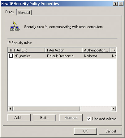
Next, we provide an in-depth example of a Cisco router with certificate authentication. Using pre-shared keys appears to be such a simple solution that some questions exist on why you would choose an alternative. Setting up two VPN peers is as simple as typing in a few commands and a single secret piece of information. However, when your environment grows from two peers to 2,000, the concept of a centralized key-handling authority becomes more attractive. This concept becomes more appealing when you consider the scenario of having to change keys. Being able to make these changes through a centralized CA is why PKI is a buzzword among the IT elite. To show the differences between a pre-shared key and a CA configuration, we will use the same Cisco router example we used previously, only changing settings that are needed for certificate authentication. All commands that remain the same will not be re-listed; we will only list new commands and commands that would need to be changed. This section will assume that you have an accessible CA already configured in your environment and available to you. Let's start our look at CA authentication by seeing what must be changed from our previous configuration. Because we are discussing authentication specifically, we know that this falls into the IKE section of the VPN; therefore, only our ISAKMP settings will be affected. Crypto maps, transform sets, encryption types, and everything else will remain the same. We only need to change the authentication type under our ISAKMP policy and then make the changes necessary to prepare our router for such authentication. The first statement in this section is identical to the one listed in the pre-shared key example: crypto isakmp policy 10 authentication rsa-sig The change is reflected in the second line of the section. The authentication command must reflect the use of RSA digital signatures, or rsa-sig for short. Because a certificate-based authentication scheme requires the querying of an entity outside the router for its keys, key storage and CA accessibility become important issues. If the CA is inaccessible, your router might accept an expired certificate or you might suffer an offline condition on your VPN. Storing certificates locally can help offset this problem of downtime, but at the price of taking up some of the precious router NVRAM storage. To configure your Cisco router to request a certificate whenever necessary, use the following command: MyRouter(config)# crypto ca certificate query This command prevents the storage of certificates or certificate revocation lists (CRLs) from using any of your router's NVRAM. Because these items wouldn't be found in local NVRAM, the router must take a performance hit to make a request. The next commands are probably already configured on your router. However, they are listed here because they are essential for operation with digital certificates: MyRouter(config)# hostname MyRouter MyRouter(config)# ip domain-name domain.com Host and domain names must be present in the router configuration because certificates are named with a fully qualified domain name. This means that the certificate's name is actually the hostname of the router followed by its domain name. For example, in this example, our router's certificate would be named MyRouter.domain.com. Before we go any further, we must generate the RSA key pair that we will use to request a certificate for our router. The following command is entered only once to generate the keys and is not a saved part of the configuration: MyRouter(config)# crypto key generate rsa To verify that your keys have been generated, you can use this command: show crypto key mypubkey rsa. Now we must configure the specifics so that our router knows where and how often to collect certificates: MyRouter(config)# crypto ca identity CA.COM This line specifies the domain name of the Certificate Authority and drops you into CA configuration mode. The following line is the last required line in this section. The rest are optional or used only in some environments: MyRouter(ca-identity)# enrollment url http://ca_4u This line simply specifies the URL of the CA. In this example, it is http://ca_4u. These next two lines are needed only in environments that use a Registration Authority (RA). An RA is an extra entity that caches certificates and CRLs in case the CA is down or otherwise unavailable. MyRouter(ca-identity)# enrollment mode ra MyRouter(ca-identity)# query url ldap_url If you have an RA in your environment, specify the first command. The second is also only used in an RA environment, but one that also supports LDAP. ldap_url in this example is the URL of the LDAP server. The next two optional lines specify how often, in minutes, the router will retry to get a certificate and how many times it will retry: MyRouter(ca-identity)# enrollment retry period 5 MyRouter(ca-identity)# enrollment retry count 100 The default number of minutes for the first command is 1, and the default number of retries is infinite. This last entry, which can be configured in the CA configuration mode, is regarding whether CRLs must be available to accept a certificate: MyRouter(ca-identity)# crl optional When this line is entered, if a given CRL is not available, the router still accepts the certificate in question. This could be a security concern because the certificate might have been previously revoked. However, it can keep authentication functioning even if the CA is temporarily unavailable. Now we are ready to request the CA's certificate. This is done with the following command: MyRouter(config)# crypto ca authenticate CA.COM Requesting the CA's certificate is necessary for authentication before receiving a certificate for your router. As a best practice, you might want to manually confirm this certificate after downloading it from the CA. The information used in this command should match the information specified in the crypto ca identity command: MyRouter(config)# crypto ca enroll name The previous command is used to receive a certificate for your router. After this command has been issued, you should be ready to initiate a VPN connection. The following are a couple of useful commands for auditing your router's CA capabilities: MyRouter# show crypto key pubkey-chain rsa The previous command shows details of available RSA public keys on your router. The following command lists all certificates stored on your router if you are not using query mode, which disallows certificate storage: MyRouter# show crypto ca certificates It is plain to see that setting up the use of digital certificates is more complicated than using pre-shared keys in the short haul, but in the long run, the time spent can pay you back many times over, especially in a large environment. Windows XP IPSec Configuration ExampleWindows XP Professional and Windows XP Home Edition can also effectively handle IPSec duties if properly configured. Doing so requires the addition of the IP Security Policy Management snap-in to your Microsoft Management Console (MMC) and monitoring with the IP Security Monitor snap-in. This integrated capability lies at the operating system level, and Windows XP's prevalence in many businesses will most likely make it an important player in the future of VPNs. (Other versions of Windows, including Windows 2000 and 2003, also offer similar IPSec capabilities.) IPSec VPN policy is configured on a Windows XP system using the IPSec snap-in for MMC. The console appears in Figure 7.5. Figure 7.5. MMC can be used to configure local and remote Windows XP IPSec policies via the IP Security Policy Management snap-in.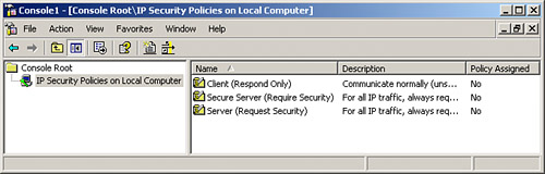 As listed in the right pane, several default security policies can be used for quick setup of Windows XP system-to-system VPNs. However, to set up an IPSec policy that will work well with other VPN products, we need to create a custom policy. This is primarily because the default authentication used for these policies is the Windows Kerberos authentication protocol. To begin to create a new security policy, follow these steps:
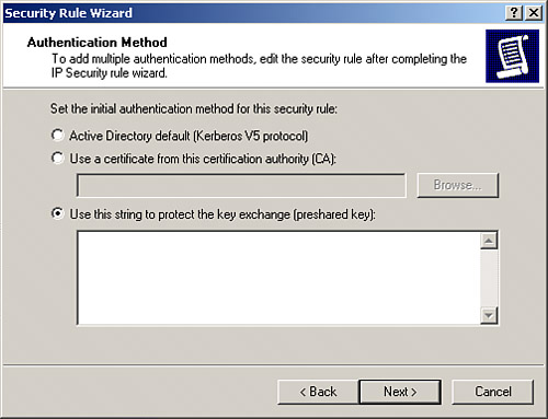
The Security Rule Wizard walks you through the process of setting IPSec parameters, such as authentication settings and IP filter settings. (IP filters are discussed further in Chapter 10.) To define IPSec parameters, follow these steps:
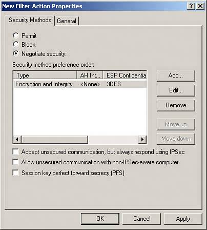
After completing the IP filter configuration settings, the next step is to tie the filter to the policy and describe how the policy should be enforced. To do so, follow these steps:
To test the settings, open a command prompt and try to ping a host on the remote subnet in question. After security is negotiated, the pings will get through if everything is configured correctly. This can be confirmed by checking the IP Security Monitor screen to show active security associations after the device is successfully pinged. Figure 7.9 shows the IP Security Statistics screen, which can be loaded by right-clicking a hostname in the IP Security Monitor and selecting Statistics. The IP Security Statistics screen contains many different counts related to IKE and IPSec activity, including several types of failures. Figure 7.9. We can use IP Security Monitor to observe statistics regarding the host's IPSec operations.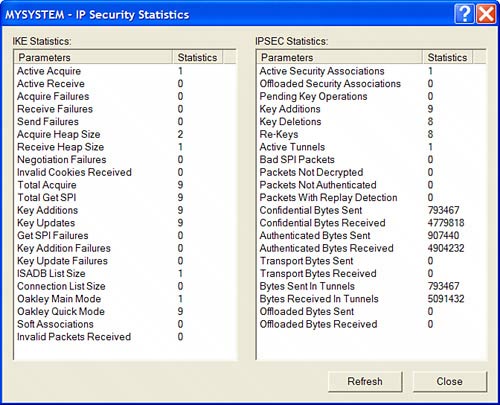 |
|
EAN: 2147483647
Pages: 230