Configuring the Cisco PIXASA
Configuring the Cisco PIX/ASAComplete configuration of the Cisco PIX is beyond the scope of this book. However, we can cover some of the initial steps required to set up the PIX and to allow an administrator access to the graphical user interface (GUI), the Adaptive Security Device Manager (ASDM) (previously known as the PIX Device Manager [PDM] for software versions previous to 7.0). To initially configure a PIX out of the box, connect a serial connecter to the console port of the PIX (which is typically outlined with a light blue color). Use the blue serial port cable that came with the PIX. If you cannot find that cable, you may also use a null modem or a rollover cable. The serial port settings in the terminal emulation software on the PC should be as listed in Table 6-1.
After the console connection has been established, start up the terminal emulation software (Microsoft Windows typically comes with HyperTerminal, and you can alternatively use TeraTerm Pro) with the settings in Table 6-1. The PIX command prompt should immediately appear (if not press the Enter button on the keyboard): pixfirewall> Next, type the enable command to access the privileged mode of execution. By default, the enable password on a new PIX is not set: pixfirewall> enable Password: pixfirewall# By default, the enable command assumes that the user is trying to access privilege level 15 (the highest privilege level). To begin configuring the PIX for basic network access, several actions must be performed:
Assigning IP Addresses to the Firewall InterfacesTo communicate on the network, the firewall needs to have IP addresses assigned to the firewall interfaces. The process of doing this changed between PIX/ASA version 6.x and 7.x, but the fundamental steps are the same: Enable the interface, configure the interface itself, and assign an IP address to the interface. Assigning IP Addresses in PIX 6.xTo assign IP addresses to the PIX interfaces, the administrator must enter configuration mode. Because the PIX uses a command interface that is similar to IOS, administrators enter configuration mode as they would on a Cisco IOS-based router: firewall# configure terminal firewall(config)# When in configure mode, the next item is to enable the interfaces. The PIX interfaces are administratively shut down in the default configuration. To enable the interfaces, use the interface hardware-id hardware-speed command: firewall(config)# interface ethernet0 auto firewall(config)# interface ethernet1 auto By default, the Ethernet0 (or FastEthernet0) hardware-id is considered the outside interface and the Ethernet1 (or FastEthernet1) hardware-id is considered the inside interface. The configuration of the interface itself is performed by the auto command word. This specifies that the interface speed should automatically be determined by the PIX rather than be specified by the administrator. You can also manually define the hardware speed (for example, 10 or 100). The next step to configuring the interface is to assign a name and security level to the interface. By default, the outside interface has a security level of 0; the inside interface has a security level of 100. The name that you assign is the name that you can use throughout the configuration to easily identify a given interface. For example, this allows you to use inside to refer to the Ethernet1 interface. You can use the command nameif hardware-id if-name security-lvl to configure the interface name and security level: firewall(config)# nameif ethernet0 outside security0 firewall(config)# nameif ethernet1 inside security100 With the interfaces now active and configured, the IP addresses can be assigned (it is just as possible to assign the IP addresses prior to enabling the interface, but the interfaces still will not work until enabled). Assigning IP addresses is performed at the global configuration mode. The firewall supports static IP addresses on all interfaces and can also be configured to use DHCP or PPPoE-assigned addresses on the outside interface only. To assign a static IP address, use the ip address interface-name ip-address subnet-mask command: firewall(config)# ip address outside 10.19.24.1 255.255.255.0 firewall(config)# ip address inside 192.168.122.1 255.255.255.0 To make sure that the PIX can communicate with devices on both sides, ping the address of a system on either interface: firewall(config)# ping 10.19.24.100 10.19.24.100 response received -- 0ms 10.19.24.100 response received -- 0ms 10.19.24.100 response received -- 0ms firewall(config)# ping 192.168.122.226 192.168.122.226 response received -- 0ms 192.168.122.226 response received -- 0ms 192.168.122.226 response received -- 0ms firewall(config)# Assigning IP Addresses in PIX/ASA 7.xFor the PIX/ASA 7.0 software, the commands that need to be run have changed, but the necessary steps are the same: Enable the interface, configure the interface itself, and assign the interface IP address. From the global configuration mode, access the interface configuration mode for the interface that you want to configure by running the interface interface-name interface-number command: firewall(config)# interface ethernet 2 firewall(config-if)# When you are in the interface configuration mode, you can perform all the interface configuration and IP address assignments. To enable the interface, run the no shutdown command. To name the interface, run the nameif name command. To assign the security level, run the security-level number command. To configure the speed and duplex settings on the interface, run the speed {auto | 10 | 100 | 1000 | nonegotiate} command and the duplex {auto | full | half} command. Examples of these commands follow: firewall(config-if)# no shutdown firewall(config-if)# nameif dmz01 firewall(config-if)# security-level 50 firewall(config-if)# speed auto firewall(config-if)# duplex auto Configuring the IP address is a matter of running the ip address ip-address [mask] or the ip address dhcp [setroute] command. The setroute option enables you to configure the firewall to use the route assigned by the DHCP server as the default route for the firewall. Unlike previous versions of software, PPPoE is no longer supported, and DHCP addresses can be assigned to any interface (not just the outside interface). In most cases, you need to assign a static IP address, as shown here: firewall(config-if)# ip address 10.21.67.17 255.255.255.240 Repeat these commands for all interfaces that need to be configured. Note Like most Cisco devices, changing the configuration only changes the running configuration. For the changes to be considered permanent and committed to memory, they must be saved to NVRAM. For PIX software running 6.x and earlier, this is done by running the write memory command at the privileged mode of execution: firewall# write memory For PIX/ASA software running 7.x and newer, this is done by running the copy running-config startup-config command: firewall# copy running-config startup-config You need to do this anytime you are finished running commands and are ready for the firewall configuration to be made permanent. Configuring the Firewall Name, Domain Name, and PasswordsNow that the firewall has been assigned IP addresses and the interfaces are functioning properly the next step is to configure some basic firewall configuration values such as the firewall host name, domain name, and passwords. The commands to perform these configurations are the same for all versions of the PIX/ASA software. You can configure the host name by running the hostname name command, and the domain name is configured by running the domain-name domain command from the global configuration mode: firewall(config)# hostname houqepixfw01 houqepixfw01(config)# domain-name houqe.lab There are two passwords that the PIX/ASA uses by default (and you are not using any form of AAA authentication). The first is known as the login password and is used to authenticate remote access via Telnet or SSH. The command to set the login password is passwd password: houqepixfw01(config)# passwd ReallyDifficultPassword The second is known as the enable password and is used to access the global configuration mode and to provide ASDM/PDM access. The command to set the enable password is enable password password level level and is shown here. The level syntax is not required, and if left blank defaults to privilege level 15. You can set multiple passwords, each granting access to a different privilege level. houqepixfw01(config)# enable password DifferentPasswordThanPasswd At this point, the firewall is able to authenticate administrative access and remote management access connections (although it still needs to be configured to allow remote management access). Configuring the Firewall Routing SettingsWith IP connectivity established, the next step is to configure routing for the firewall. The firewall supports both static routes and dynamic routing using Open Shortest Path First (OSPF; for more information about configuring OSPF routing, see Cisco ASA and PIX Firewall Handbook [Cisco Press]). You can configure static routes on all software versions by running the route interface-name ip-address netmask gateway-ip [metric | tunneled] command. This same command can be used to set the default route for the PIX as follows: houqepixfw01(config)# route outside 0.0.0.0 0.0.0.0 10.21.67.2 1 The value 1 at the end of the route command specifies the metric to the next hop and is optional. In general, the default route will point to the next-hop router for the firewall on the internet, for example pointing to the Internet service provider router. Configuring the Firewall for Remote Management AccessThe PIX/ASA firewall supports three primary methods of remote management access:
Both Telnet and SSH are used to provide CLI access to the firewall, whereas the ASDM/PDM provides an HTTPS-based GUI management console. Configuring Telnet AccessTelnet remote management is the simplest, yet least secure, method of remotely managing the firewall. The reason for this is that Telnet does not encrypt the data in transmit and in fact sends the data in cleartext. This makes it easy for a malicious user to capture the data and learn things like the usernames and passwords required to gain access to the firewall. Because of this deficiency, it is not possible to access a PIX/ASA firewall over the outside interface using Telnet alone (although PIX/ASA does support Telnet to the outside interface if it is protected by IPsec). The configuration to allow Telnet access is the same for all PIX/ASA software versions. This is done by running the telnet {hostname | ip-address mask interface-name} command at the global configuration mode: houqepixfw01(config)# telnet 10.21.120.15 255.255.255.255 inside You can restrict Telnet access to certain IP addresses or hosts by defining the appropriate subnet mask. For example, in the preceding command, only the host with IP address 10.21.120.15 is allowed to connect to the firewall. You can also define the interface that the Telnet access will be permitted to by using the appropriate interface name (for example, inside or dmz01, if you named an interface dmz01). Because of the general insecurity of Telnet, and because SSH provides the same functionality to the firewall, use SSH instead of Telnet. Configuring SSH AccessConfiguring SSH is a little more involved than configuring Telnet access because for a connection to be established using SSH the target host needs to have an RSA key pair for identity certificates. Therefore, configuring SSH access is actually a series of smaller steps that must be performed:
The procedure for assigning the host and domain name for the firewall was covered previously in this chapter. The reason why it is important to do this is that the RSA key pairs use the host and domain name in the key-generation process. Generating and saving the RSA key pair is performed in one of two methods depending on whether you are using PIX 6.x or PIX/ASA 7.0. For PIX 6.0, you can generate the RSA key pair by running the ca generate rsa key key-size command from the global configuration mode: houqepixfw02(config)# ca generate rsa key 1024 For <key_modulus_size> >= 1024, key generation could take up to several minutes. Please wait. Keypair generation process begin. .Success. houqepixfw02(config)# One of the bigger deficiencies of the PIX 6.x software is that, unlike every other configuration setting, the RSA keys are not saved when you issue the write memory command. Instead, they need to be saved separately using the ca save all command from the global configuration mode: houqepixfw02(config)# ca save all For the PIX/ASA 7.x software, generating the RSA keys requires the use of the following command: crypto key generate rsa [ usage-keys | general-keys ] [ label key-pair-label ] [ modulus size ] [ noconfirm ] As a general rule, the only syntax required is the following: houqepixfw01(config)# crypto key generate rsa modulus 1024 INFO: The name for the keys will be: <Default-RSA-Key> Keypair generation process begin. Please wait... houqepixfw01(config)# You can specify a modulus size of 512, 768, 1024 (the default size), or 2048. Unlike previous software versions, the RSA keys are saved when you save the firewall configuration (for example, by running the command copy running-config startup-config). After the RSA keys have been generated, the step to actually permit SSH access to the firewall is the same for all software versions and is similar to how Telnet access is permitted. Just run the command ssh ip-address mask interface command: houqepixfw01(config)# ssh 10.21.120.15 255.255.255.255 inside Like Telnet, SSH can be restricted to subnets or hosts. Unlike Telnet, SSH can also be configured for remote access to the outside interface. PIX/ASA 7.x also supports running SSHv1 or SSHv2 (previous software versions supported a variant of SSHv1 1 known as version 1.5). In general, SSHv2 is considered more secure, and the firewall can be restricted to only supporting SSHv2 by running the ssh version 2 command. Configuring ASDM/PDM AccessIn addition to the CLI management methods, PIX/ASA firewalls support a GUI for remote management. For PIX 6.x, this management interface is known as the PIX Device Manager (PDM). For PIX/ASA 7.x, this management interface is known as the Adaptive Security Device Manager (ASDM). Both are extremely similar to each other, with the ASDM being the logical upgrade and replacement for the PDM. The ASDM/PDM functions as a web-based management interface using a small web server running on the firewall and Java plug-ins on the client computer to function. Configuring the ASDM/PDM requires a couple of steps that are the same for all software versions. First, you must ensure that you have downloaded and installed the ASDM/PDM software on the firewall (by default, it is included with the firewall). Second, you need to enable the HTTP server on the firewall by running the http server enable command. Third, you need to permit HTTP access in a manner similar to Telnet and SSH by running the http ip-address mask command: houqepixfw02(config)# http server enable houqepixfw02(config)# http 10.0.0.0 255.0.0.0 inside Historically, access to the ASDM/PDM is performed by connecting to the web server using a web browser such as Microsoft Internet Explorer. The ASDM also can use a Java-based application that allows you to launch ASDM without needing to start a web browser, as shown in Figure 6-2. Figure 6-2. Cisco ASDM Launcher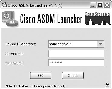 Just enter the IP address or host name of the firewall and the appropriate username and password. If you do not use any form of AAA, leave the username blank and enter the enable password to connect to the firewall. The ASDM will parse the running configuration of the firewall and display the General Device Information screen, as shown in Figure 6-3. The ASDM is an intuitive GUI interface that you can use to configure the firewall in lieu of the CLI. Figure 6-3. General Device Information Screen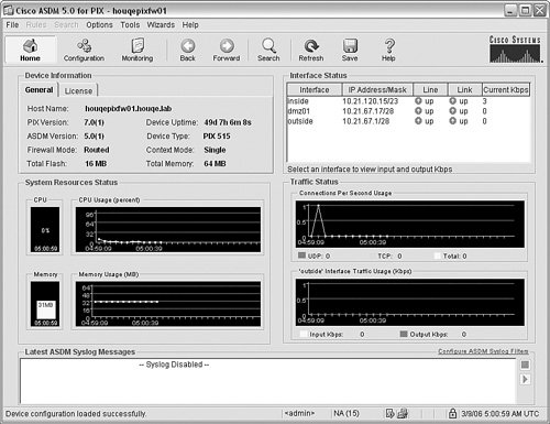 Configuring NAT Settings for Outbound AccessAfter the default route has been set, the PIX/ASA is almost ready to pass traffic between the inside, higher-security interface and the outside, lower-security interface. In most situations, to provide for this outbound traffic functionality you need to configure NAT because the firewall will typically be hiding the internal network IP addresses from the external network resources using NAT. This is not a requirement, however (although it is generally recommended), and the PIX/ASA 7.0 in particular does not require NAT for outbound communications. The configuration (or lack thereof) for NAT differs depending on whether you are using PIX 6.x or PIX/ASA 7.0. Configuring NAT for PIX 6.xOutbound access for the PIX firewall generally requires the configuration of two policies. First, define the translation method that is going to be used for the outbound requests. Second, ensure that if an ACL exists for the given network interface that an access rule is defined to allow the traffic in question. By default, the PIX firewall allows all traffic from a higher-security interface to a lower-security interface, by virtue of the fact that there is not a default ACL on any interface. There are two primary methods of performing translation: a static translation or a dynamic translation. Static translations are essentially a one to one mapping of internal addresses to external addresses. Therefore, they require that the internal address not change and consequently do not tend to be an effective method of providing outside access to a bunch of hosts. Instead, they tend to be used in conjunction with ACLs to provide access to internal resources from external sources (we address this configuration later in this chapter). Dynamic translation uses NAT/PAT to dynamically assign addresses (or ports) to internal hosts that require external access. The firewall keeps track of which communications sessions belong to each internal host and allows the firewall to perform the required translations. To configure dynamic NAT, you need to build a NAT rule. The simplest way to do this is to specify what traffic is to be translated using the nat command and then set up a global pool using the global command. The nat command is used to define what local addresses will be included for NAT. The syntax of the command is this: nat [(local-interface)] id local-ip [mask [ dns ] [ outside | [ norandomseq ] [max_conns [emb_limit]]] The id and local-ip syntax are used to define the local IP addresses that will be included in the corresponding NAT translation (defined by the ID). A notable exception to this is the nat 0 access-list acl-name command, which configures the firewall to not use NAT for any addresses that match the corresponding ACL. This is typically used for access across VPN connections. In most other cases, you would define the NAT addresses as follows: houqepixfw02(config)# nat (inside)1 0.0.0.0 0.0.0.0 In this case, we have specified to use NAT for all addresses. If we only wanted NAT to be used for addresses on the 10.1.1.0/24 subnet, we could have replaced the local-ip and mask with 10.1.1.0 and 255.255.255.0. After you have defined what local addresses should use NAT, the next step is to configure the global pool. The global command is used to define the pool of global addresses that will be used by the translation rule. The easiest way to think of the global addresses is that these are the external addresses that the internal clients will appear to be coming from when they access external resources. You can specify one or more global addresses in the pool. If you specify a single address instead of performing NAT, the firewall will automatically perform PAT instead. The syntax of the command is this: global [(if-name)] nat-id {global-ip [-global-ip] [netmask global-mask]} | interface The interface syntax can be used to specify to use the interface IP address for PAT instead of defining an additional IP address for the global pool. This is particularly useful in cases where there is a single address available for use (for example, when using a PIX firewall in a SOHO environment over a broadband connection such as digital subscriber line [DSL] or cable modem). The following command configures a global pool on an outside interface to use addresses 10.21.67.40/28-10.21.67.45/28: houqepixfw02(config)# global (outside)1 10.21.67.40-10.21.67.45 netmask 255.255.255.240 When all the IP addresses are being used by NAT, the firewall will automatically switch to using PAT (assuming that a PAT statement has been configured) to allow more addresses out. Alternatively, if you only have the IP address that is assigned to the interface, you can simplify the global command as follows: houqepixfw02(config)# global (outside)1 interface outside interface address added to PAT pool houqepixfw02(config)# Assuming that there is not an ACL that needs to be configured, the hosts defined by the NAT translation rule will have outbound access. Configuring NAT for PIX/ASA 7.xA major difference between the PIX/ASA 7.x software and previous versions is that by default the firewall does not require NAT and will allow outbound access with no additional configuration required. Of course, if your environment requires NAT (which most Internet-connected firewalls require), you must execute the appropriate NAT configuration commands on the firewall. To require NAT for communications, you must first run the nat-control command (no additional syntax). When NAT control is disabled (the default), the firewall allows communications with outside hosts without the configuration of a NAT rule. When NAT control has been enabled, the next step is to run the nat and global commands. For the PIX/ASA 7.x, the nat and global syntax differs slightly: nat (real-ifc) nat-id real-ip [mask [dns] [outside] [[tcp] tcp-max-conns [emb-limit]] [udp> udp-max-conns] [norandomseq]] global (mapped-ifc) nat-id {mapped-ip [-mapped-ip] [netmask mask] | interface} In this particular case, however, the actual commands are the exact same command syntax for previous versions of software. Therefore, running all three commands might look like this: houqepixfw01(config)# nat-control houqepixfw01(config)# nat (inside)1 0.0.0.0 0.0.0.0 houqepixfw01(config)# global (outside)1 10.21.67.10-10.21.67.14 netmask 255.255.255.240 In this case, NAT control is enabled, a NAT pool for all internal addresses is configured, and a global pool from 10.21.67.10 through 10.21.67.14 is configured. At this point, internal hosts can access external resources using NAT. Alternatively, if you only have the IP address that is assigned to the interface, you can simplify the global command as follows: houqepixfw01(config)# global (outside)1 interface INFO: outside interface address added to PAT pool houqepixfw01(config)# Configuring the ACLsControlling traffic is the cornerstone of all firewalls, and the PIX/ASA controls the flow of traffic through the firewall by implementing ACLs. PIX/ASA ACLs are essentially linked lists of values known as ACL entries (ACEs) that are parsed in a top-down manner with entries at the top of the ACL being processed before entrees further down the ACL are processed. This processing is performed in a first-match manner, which means that as soon as the data being processed by an ACL is matched to an ACE, the ACL stops being parsed and the action defined in the matching ACE is performed. Therefore, ensure that when you build your ACLs you place entries to permit traffic ahead of entries that deny traffic; otherwise, as soon as the data matches an ACE that denies the traffic, the traffic will be blocked, and the ACE that permits the traffic will never be processed. The configuration and implementation of ACLs is a two-step process:
Defining the ACL and Implementing the ACEsThe PIX/ASA supports a number of different types of ACLs:
You can configure multiple types of ACLs on a PIX firewall and define multiple ACLs of the same type. Doing so enables you to define purpose-based ACLs. A purpose-based ACL means that the ACL is defined for a given purpose and the ACEs in the ACL have been written explicitly for that purpose. Doing so enables you to use different ACLs to control and filter traffic in multiple situations. For example, you might build one ACL to control traffic coming from the Internet to a DMZ segment and then build another ACL with different ACEs to control traffic coming from the DMZ to the internal network. Building an ACL is a pretty straightforward procedure that typically requires defining the following elements:
ACLs are built on all software versions by running the access-list command with the appropriate parameters. Table 6-2 shows the parameters available for an extended ACL.
The syntax that the parameters are input in an extended ACL is as follows: access-list id [line line-number] [extended] {deny | permit} {protocol | object-group protocol_obj_grp_id} {src_ip mask | interface ifc_name | object-group network_obj_grp_id} [operator port | object-group service_obj_grp_id] {dest_ip mask | interface ifc_name | object-group network_obj_grp_id} [operator port | object-group service_obj_grp_id | object-group icmp_type_obj_grp_id] [log [[level] [interval secs] | disable | default]] [inactive | time-range time_range_name] Although this may seem like a lot of information, many of the values are optional and not necessary in most cases. Most access-list entries use an abbreviated syntax: access-list id {deny | permit} protocol source destination operator port For example, if you wanted to define an access-list entry to permit HTTP traffic from any host to a web server, you would run the following command: houqepixfw01(config)# access-list out_in_01 permit tcp any host 10.21.67.2 eq http In this example, we defined an ACL ID of "out_in_01" and configured it to permit TCP port 80 (HTTP) from any source to the destination 10.21.67.2. If you want the same ACL to also permit SMTP traffic to a different server, run the following command: houqepixfw01(config)# access-list out_in_01 permit tcp any host 10.21.67.3 eq smtp You can view the ACL to see that both lines have been added to the same ACL by running the following command (the implicit deny ip any any rule at the end of all ACLs is not shown, which is a good reason to explicitly add it to all ACLs): houqepixfw01(config)# show access-list out_in_01 access-list out_in_01; 2 elements access-list out_in_01 line 1 extended permit tcp any host 10.21.67.2 eq www (hitcnt=0) access-list out_in_01 line 2 extended permit tcp any host 10.21.67.3 eq smtp (hitcnt=0) The hitcnt value displays whether any packets have matched the ACE, which can assist in troubleshooting connectivity through the firewall. For example, if you do not see the hitcnt value increasing when traffic that is supposed to be matching the ACL is being transmitted, it might mean that the ACL is misconfigured. A common example of that happening would be accidentally specifying the wrong protocol for the ACL (for example, using TCP when you should have used UDP). After the ACL has been defined, the firewall still is not using the ACL. For that to occur, you must assign the ACL to an interface. Assigning the ACL to an InterfaceFundamentally, there are two methods of filtering traffic: ingress filtering and egress filtering. Ingress filtering defines filtering traffic that is coming into a trusted network from an untrusted network. Egress filtering defines filtering traffic that is coming from a trusted network to an untrusted network. For PIX software version 6.x and below, all ACLs were applied to traffic coming into an interface. So, for example, if you wanted to apply an ACL for traffic coming from the internet to a DMZ segment, you would apply the ACL to the outside interface of the firewall, thus allowing it to filter traffic coming into the firewall on the outside interface. This would be an example of an ingress filter. To build an egress filter (for example, to filter traffic from the inside network to the outside network), you would apply the appropriate ACL to the inside interface. With the PIX/ASA software 7.x and above, the concept of applying ACLs became a little bit more complex, but at the same time more flexible. Rather than only being able to apply an ACL to inbound traffic on a given interface, with the 7.x software you can apply an ACL to an interface and define whether it applies to traffic entering the interface (in) or exiting the interface (out). This flexibility allows you to do things such as define an egress filter and apply it to outbound traffic on the outside interface. Regardless of which software the firewall is running, ACLs are applied to an interface by running the access-group command. The only real difference between 6.x and 7.x is the ability to specify in or out in the syntax as follows: access-group access-list {in | out} interface interface-name [per-user-override] For example, if you want to apply the ACL that was previously defined (ACL out_in_01) to the outside interface on the firewall, you run the following command: houqepixfw01(config)# access-group out_in_01 in interface outside At this point, assuming that you have your translation rules configured accordingly, the traffic that has been permitted or denied in the ACL out_in_01 will be filtered on the outside interface accordingly. Configuring Logging on the FirewallOne of the most valuable capabilities of any firewall is the ability to log events so that the administrator can be informed of and aware of what is going on with the firewall. Cisco PIX/ASA firewalls use syslog for the logging of all events on the firewall (syslog and logging in general is discussed in much greater detail in Chapter 12, "What Is My Firewall Telling Me?"), which allows an administrator to be able to read/parse the logs for important events or events that may require additional action (for example, events that indicate a misconfiguration of the firewall may be occurring). In general, PIX/ASA firewalls support the following commonly used logging destinations:
Regardless of the logging method implemented, it is important to ensure that the firewall has the correct date and time (either by manually entering the date and time or using NTP to automatically configure the date and time) to ensure that the logs can be easily interpreted. For more information about configuring the date and time on PIX/ASA firewalls, see the Cisco ASA and PIX Firewall Handbook (Cisco Press). Configuring Console, Monitor, or ASDM LoggingConsole, monitor, and ASDM logging all function in a similar manner in that they are all designed to output the logging results to the management interface (the CLI in the case of console and monitor logging or the ASDM GUI in the case of ASDM logging). Consequently, they all use similar variations of the logging command. Before you can enable any particular method of logging, the first step is to enable logging in general on the firewall by running the command logging on from the global configuration mode of execution. This command is the same command for all versions of PIX/ASA software. To enable console logging run the command logging console [logging-list | level]. The logging-list syntax enables you to refer to a list of defined logging level, event class, and message IDs that have been previously defined by the logging list name {level level [class event-class] | message start-id[- end-id]} command. The level syntax defines the maximum level of system log messages to log. For example, if you want to log debug level and below, you run the following commands: houqepixfw01(config)# logging on houqepixfw01(config)# logging console debug %PIX-5-111008: User 'enable_15' executed the 'logging console debug' command. %PIX-3-710003: UDP access denied by ACL from 10.21.120.178/137 to inside:10.21.121.255/137 This command causes the firewall to display all log messages to the console session of the firewall. If you are using Telnet or SSH to connect to the firewall and you want to have the log messages display in the Telnet or SSH session, run the logging monitor [logging-list | level] command. This causes the firewall to log all messages to Telnet or SSH sessions, but they will not actually be displayed to the active Telnet or SSH session until you also run the command terminal monitor. Terminal monitor enables the display of the syslog messages to the current Telnet or SSH session. For example, if you want to log debug level and below and display the syslog messages on the current SSH session, run the following commands: houqepixfw01(config)# logging on houqepixfw01(config)# logging monitor debug houqepixfw01(config)# terminal monitor %PIX-5-111008: User 'enable_15' executed the 'terminal monitor' command. %PIX-3-710003: UDP access denied by ACL from 10.21.120.178/137 to inside:10.21.121.255/137 You can stop the display of syslog messages, while still having the firewall perform monitor logging, by running the command terminal no monitor. These commands are the same for all versions of the PIX/ASA software. Caution Although logging at debug level can assist in troubleshooting a problem, it should be strongly cautioned before implementing on a production firewall (because of the volume of data that will be logged). Debug logging can cause events to be lost from the logging buffer due to volume of data and in extreme circumstances can have a negative impact on the performance of the firewall due to the amount of logging messages. In some cases, the only method of recovering from logging debug messages is to reboot the firewall. You can configure ASDM logging either at the CLI using the logging asdm [logging-list | level] command or through the ASDM interface. To use the ASDM, you need to launch the ASDM and login to the firewall. When you are at the default home screen, as shown in Figure 6-3, click the Configuration button in the toolbar. In the Features pane, click the Properties button and then navigate through the feature tree to select Logging Filters, as shown in Figure 6-4. Figure 6-4. Logging Filters Screen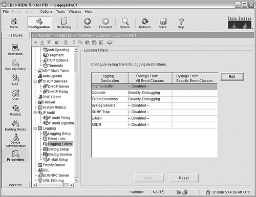 As you can see, the previous commands we ran are shown in this screen, and you can edit or change any of the depicted logging settings. To enable ASDM logging, click ASDM and then click the Edit button to display the Edit Logging Filters screen, as shown in Figure 6-5. Click the Filter on severity button and select the appropriate severity level from the drop-down list (in this case, Debugging was selected). When you have finished, click OK. Figure 6-5. Edit Logging Filters Screen The last step is to save the configuration changes to the firewall to cause the firewall to use the updated configuration. You can do that by clicking Apply in the Logging Filters Screen shown in Figure 6-4. If you return to the home screen (by clicking the Home button in the taskbar), you will now see the syslog messages being displayed in the ASDM interface in the Latest ASDM Syslog Messages group box, as shown in Figure 6-6. Figure 6-6. ASDM Log Messages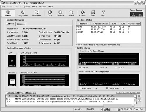 Configuring Logging to a Remote Syslog ServerAlthough logging to the console, monitor or ASDM can be handy for troubleshooting problems and viewing log messages while logged in to the firewall, if you need to store logs for long-term archive or auditing purposes, you need to configure the firewall to transmit the syslog messages to a remote syslog server. Like the previous logging methods, you must first enable logging in general by running the logging on command. Then, you need to define what syslog server the firewall should transmit the syslog messages to by running the logging host interface-name syslog-ip [tcp/port | udp/ port] [format emblem] command. At a minimum, you need to define the interface that the syslog server is connected to (typically the inside interface) and the IP address of the syslog server. After you have done this, you need to define the level of syslog messages that will be logged by running the logging trap [logging-list | level] command. For example, if you want to transmit syslog messages to the syslog server running on 10.21.120.10 and you want to transmit logging levels errors or above, you run the following commands: houqepixfw01(config)# logging host inside 10.21.120.10 houqepixfw01(config)# logging trap errors At this point, the firewall will transmit the syslog messages to the syslog server (in this case, using the default port UDP 514). |
EAN: 2147483647
Pages: 147