Cable-based and LAN-based Configurations
| Cable-based (serial) and LAN-based configurations dictate how the primary and secondary firewalls are linked together to provide failover support. The following provides an overview of each.
Cable-based ConfigurationsA cable-based configuration ”also known as serial-based ”requires a special serial cable from Cisco to connect the firewalls. The cable can be up to 6 feet in length and connects the dedicated failover port on the PIX models 515 and above. Before software version 5.2, the maximum speed that software provided across the serial cable was only 9.6Kbps; however, it's now 115Kbps. This connection provides a means to replicate RAM information from the active to the standby firewall and provides detection of power loss on the other side. However, the limiting factor for this setup is that the distance between the firewalls can be only 6 feet.
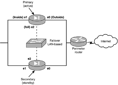
LAN-based ConfigurationsA LAN-based configuration has been introduced in version 6.2 of the PIX firewall software. This enables the use of a dedicated Ethernet interface to perform the same functions as the serial cable-based configuration does. However, you are no longer restricted by the 6- foot distance limitation. Some restrictions do exist when using LAN-based configurations. The two interfaces dedicated for LAN-based failover must be on the same subnet, so the two firewalls can't travel through a router. Another limitation is that the interface is completely dedicated to the failover monitoring and configuration and therefore should not be on the same LAN/broadcast domain as any other device. When linking the two firewalls, you must use a dedicated hub, switch, or VLAN. Please note that you cannot use a CAT 5 crossover cable for this connection. Figure 11.3 shows a typical LAN-based failover configuration. Figure 11.3. A LAN-based configuration.
|
EAN: 2147483647
Pages: 218
