Introduction to Failover
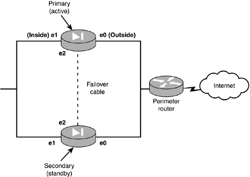
| The PIX firewall provides the capability to support a backup-generator-style of fault tolerance. If the primary unit goes down, the secondary unit comes online to take its place. However, the secondary does not provide load-balancing capabilities, but rather a hot standby approach if the primary fails. To support failover, firewalls are interconnected with a cable to provide a means of monitoring and configuring each other. This interconnection is provided by special serial cables or via a dedicated Ethernet interface cable called a LAN -based cable. Figure 11.1 displays a typical configuration of a primary and secondary firewall configuration. Figure 11.1. A basic failover configuration. Non-stateful FailoverNon-stateful failover is the most basic solution of the failover options. When two firewalls are interconnected with either a serial cable or dedicated Ethernet interface, they send only RAM configuration information and session information across. If the primary (active) firewall cannot be detected across any interface, the secondary (standby) firewall assumes the active role, subsequently inheriting the primary's IP addresses and MAC address, and effectively become the operating firewall. The primary, on the other hand, assumes the IP address and MAC address of the secondary firewall and stops passing traffic. When this happens, all xlate and connection table entries are lost and will have to be reestablished. For example, if Jack had an FTP connection through the firewall, when failover occurred Jack would have to reestablish a connection through the firewall to make his FTP operational. Figure 11.1 is a non-stateful failover configuration.
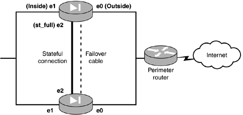
Stateful FailoverStateful failover behaves in a similar way to non-stateful when a failover occurs. However, xlate and connection table information is maintained continually across a second dedicated Ethernet connection between the firewalls. When failover occurs, the secondary already contains the xlate and connection table information, providing users with a seamless failover. For example, if Jack had an FTP connection before the failover, that connection would still be maintained in the xlate and connection tables when the secondary took over. Figure 11.2 shows a stateful failover configuration. Figure 11.2. A stateful failover configuration. The second Ethernet connection used for stateful failover must be a dedicated link between the two firewalls. The link can be FDDI, 100Mbps Fast Ethernet, or Gigabit Ethernet. When using 100Mbps Fast Ethernet, the connection is made using either a CAT 5 crossover cable or a dedicated full-duplex VLAN switch connection. Figure 11.2 shows the stateful connection using Ethernet 2 interfaces.
|
EAN: 2147483647
Pages: 218

