3.5 Set-Top-Box SOC Example
3.5 Set-Top-Box SOC Example [1]
[1] Copyright 2002, Sonics, Inc. Portions reprinted with permission.
Future generations of STBs must embrace SOC technologies in order to deliver new levels of performance while cutting costs.
STB architects and designers face tough challenges in developing increasingly complex systems; these problems are compounded by aggressive TTM goals. STB design challenges can be met only through core reuse, better tools, new design methodologies, and approaches that promote standardization.
During this STB design exercise, a system model was built and simulated using the Sonics FastForward Development Environment. The architecture employs a DRAM subsystem in conjunction with a SiliconBackplane. Among the advantages of this pairing are the following:
-
End-to-end performance guarantees. The cores and the SiliconBackplane cooperate to seamlessly provide quality-of-service guarantees for each discrete dataflow.
-
Reduced costs through reduced complexity and efficient sharing of memory and interconnect resources.
-
High-level functional decoupling enabled by system dataflow service abstractions.
-
Predictable timing behavior reduces reliance on overdesign of subsystems. Core data buffers are reduced or eliminated, and buffering requirements overall are more easily assessed.
STB Application Description
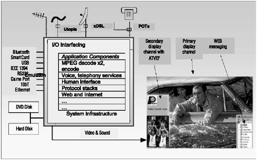
This example takes the common digital TV facilities of today's STBs and adds new Internet and multimedia functions. These features include DVD, the Advanced Television Enhancement Forum protocol, time-shifting (instant fast-forward and review, which allows the viewer to be away from the TV without missing any parts of a program), VoIP, video telephony, and even home video editing. Family members can be watching TV, Web surfing, recording a favorite program from another TV channel, keeping track of sports events on a third channel, making a VoIP telephone call, and listening to an Internet radio station upstairs over a Bluetooth link all at once. On another occasion, there could be a videophone call taking place while someone reviews a favorite football play using the time shift feature of the STB.
Figure 3.6 provides an overview of the application with the many interface devices and components . Interconnect and unified memory has long been an attractive proposition with its conceptually simple, clean architecture.
Figure 3.6. Application Overview
STB Characteristics
Delivering multiple functions simultaneously , the STB is a multitasking, software-driven platform with a mixture of general and application-specific processors. Numerous processes execute concurrently, most with critical, hard real-time dataflows such as video refresh. To accommodate these processes, both video compression and decompression , plus a host of other digital signal-processing functions, are required.
Though the proposed STB resembles other multimedia platforms, some important factors define and differentiate it. Most importantly, price constraints dictate using low-cost, commodity DRAM in a unified, memory subsystem. STB cost and performance depend on how efficiently the DRAM and communications infrastructure support the mixture of concurrent, high-bandwidth, real-time, and non-real -time traffic.
Dataflows are predominantly between cores and DRAM with little processor-to-processor traffic. DRAM provides the necessary buffering between processes ranging from small bit-stream FIFOs to video frame buffers. To function correctly, interconnect and memory systems must handle the collective peak bandwidth of all real-time flows under worst-case conditions (approaching 1GB/s). The system needs to provide a broad range of performance guarantees with differing quality of service since the demands of individual dataflows vary radically . (Video refresh requires a significant percentage of system bandwidth while audio needs orders of magnitude less.)
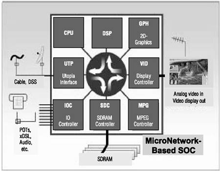
The STB shown in Figure 3.7 uses a unified communications backbone, the Sonics SiliconBackplane, to connect all cores. Use of a unified Interconnect and unified memory has long been an attractive proposition with its conceptually simple, clean architecture.
Figure 3.7. STB SOC System Block Diagram
Previous attempts at unification in real-time or multimedia applications have been marred by deficient and unpredictable performance. Design errors in these systems have been recognized as among the most costly to resolve and the hardest to manage. To meet performance goals and retain predictability, typical designs avoid shared resources and employ multiple buses and memories. The new SOC architecture directly addresses many of these issues.
Dataflow Concepts and Resource Sharing
Resource sharing traditionally trades hardware for behavioral complexity. Increasing the number of sharing or shared units decreases costs, but it increases behavioral complexity by layering extra dimensions of interaction on complex core timings. In this time domain, formalisms, design methodologies, and tools are relatively undeveloped.
A prime objective of this STB project is to reduce complexity by developing a model with dedicated, virtual channels for each dataflow. The SiliconBackplane supports this model with features that enable bandwidth and latency guarantees for each dataflow channeled across it.
The proposed system permits data streams to be analyzed in isolation, processes to execute independently without resource conflicts, and bandwidth to be managed as an assignable commodity. This level of determinism reduces system complexity by recasting the integration challenge as
-
A rigorous definition of dataflows and a determination of their individual requirements
-
Development of a system configuration to serve each and all of those requirements
DRAM Block Accesses
The DRAM controller model used here provides performance guarantees that complement those of the SiliconBackplane and support the virtual channel concept. The combined memory-SiliconBackplane system can deliver predictable, high-rate data streams to cores allowing end-to-end guarantees to be made around this service. However, DRAM systems are incapable of providing high-bandwidth guarantees for random accesses and are only efficient with block accesses. Block-addressing rules apply to data streams and affect the nature of performance guarantees. The DRAM controller is responsible for turning multiple data streams into interleaved block accesses to maximize the DRAM system's efficiency.
Dataflow Analysis
To map the application to SOC hardware, a dataflow graph of all required real-time functions was defined. The graph describes functional blocks, buffering requirements, and the dataflows between blocks with their worst-case bandwidths. Partitioning the system is accomplished by mapping this graph onto processors, memory, communications resources, and time.
For instance, the MPEG functions map onto DSP time slices for audio and special purpose processors for video. In places the MPEG data paths fold onto the SiliconBackplane, which connects functional blocks with the buffering resource, the DRAM subsystem.
The resulting mapped graph defines which dataflows the SiliconBackplane will handle and the bandwidth requirements of each one.
Figure 3.8 shows one MPEG decode process that includes video and audio generation. The buffering required between processing stages is explicitly drawn and the bandwidths annotated (buffering required by the application rather than its hardware instantiation). The dotted boxes indicate how the MPEG function is partitioned into execution units. The dataflows crossing dotted boundaries represent interunit communications that need to be carried by the SiliconBackplane.
Figure 3.8. MPEG Dataflow
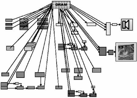
A complete dataflow graph for the STB audiovisual processing is shown in Figure 3.9. Two MPEG decoders, an MPEG encoder, VoIP, and other functions are included. It captures all real-time application functions, dataflows, and buffering. In the STB, most data buffering is handled by DRAM as shown in Figure 3.10, and all interblock flows are buffered. Redrawing the dataflow graph with a unified memory replacing the discrete FIFO illustrates the shared memory problem.
Figure 3.9. Complete STB Dataflow
Figure 3.10. Dataflow Buffer Mapping to DRAM
System Partitioning
The system architecture follows a conventional decomposition that includes a RISC and a variety of application-specific processors, I/O components, and a unified SDRAM subsystem connected by a SiliconBackplane. Partitioning is necessary since no single, general-purpose processor can achieve the performance levels required.
In the architectural definition phase, the cores and SiliconBackplane infrastructure don't need to be concretely defined. For a variety of reasons, system requirements are likely to be highly fluid during development. This highlights the value of flexibility and the ability to rapidly upgrade. Since the Sonics SiliconBackplane allows late binding decisions on the integration and configuration of cores, it is suited for this type of application.
Block Descriptions
This section describes the function, implementation, and system requirements of the cores. Each real-time dataflow is identified and expressed in terms of bandwidth needs. In SiliconBackplane terminology, each dataflow is called a thread and each thread in the dataflow model is typically unidirectional, either reading from or writing to DRAM. For example, the video core will take two MPEG-generated images and a graphics plane on separate threads and combine the pixel streams into a single output. Video input from an analog source comes into the same core and out to DRAM on its own thread. Each thread may have different natural word sizes and data rates.
SDRAM Controller (SDC)
The SDRAM controller needs to provide hard, real-time bandwidth guarantees, minimum latency, and near-peak SDRAM utilization. The projected implementation uses double-data-rate synchronous DRAMs at 75MHz and a 64-bit-wide data path with 1.2GB/s peak bandwidth. The targeted peak bandwidth utilization is above 80 percent.
External SDRAM
The target devices are JEDEC standard (PC200), 4-page, DDR-SDRAM with a 4M word deep x 16b wide DDR-SDRAM. Four of these chips provide a 64-bit interface with a total RAM of 32MB. Using 128Mb devices as a build-time option provides the same performance and double the memory capacity. Other configurations are possible with the SDC providing similar performance and guarantees.
Video I/O Device (VID)
The video I/O device captures video from a camera or analog broadcast for compression and display (time shifting) or videophone type applications. A loopback path between video in and video out is provided for system test. The video output section takes constant rate pixel streams and manipulates them for display.
The pixel processor performs color -space conversion (from YUV and YCbCr to RGB) and the video overlay function. Graphics and MPEG pictures are mixed according to the alpha channel of the overlay video page. This provides video in a window, PIP, and full graphics display under software control. The video field rate was doubled from 60Hz to 120Hz to provide a flicker-free double-scanned display and is accounted for in the bandwidth requirements.
High-Speed RISC (CPU)
The central processor of the STB is used for system coordination and control (running RTOS), plus more specific real-time multimedia tasks such as handling parts of the MPEG encode process, MPEG data stream demultiplexing , or entropy coding.
In this application, CPU performance is optimized although it is not involved in many critical real-time flows. Real-time CPU processes can easily be overallocated to meet hard guarantees about their execution rates. Good non-real-time performance is valuable in many general-purpose applications like Internet browsing.
MPEG Processor (MPG)
The MPEG core needs strong, high-bandwidth guarantees from the memory system to decode video in real time. Compared to RISC, the processing can be deeply pipelined with lax latency requirements. Various threads are used by the MPEG core including compressed input stream, decoded video output, I and B frame macro block accesses, and some for MPEG encode. The core accesses memory as blocks corresponding to 16x16 pixels (a macro block), and the memory controller guarantees a number of these blocks per second. The pixel groups in MPEG decoding can straddle several blocks so a bandwidth assignment of four times the underlying raw rate is provided. This absolute worst-case provision will rarely be used, and the surplus SDRAM bandwidth can be applied to CPU or graphics operations. The MPEG encoder translates MPEG format, 4:2:0 YCbCr to 4:2:2, easing video output pixel processing since no line buffering is required for the video I/O device. This requires a little more bandwidth from the memory subsystem. This unit also handles picture scaling for picture-in-picture functions. An input bandwidth of MPEG1 (1.5Mb/s) or MPEG2 (up to 10Mb/s from DVD source or statistical multiplexed source material) is assumed. Overall, the bandwidth assigned to the MPEG unit is conservative and can be optimized. While a worst-case model is used, a supporting external environment can simplify the core design.
Digital Signal Processor (DSP)
The DSP implements audio-processing tasks including AC3, MP3 decode and audio encode, and a V.90 modem. Data and program caches are explicitly managed by the DSP so data access can be handled as block-burst transfers for code segments and sequential-block transfers for data. A simple estimate is sufficient for peak DSP-bandwidth requirements.
Utopia Interface (UTP)
A UTOPIA_II interface attaches to one or more cable modems or transceivers and supports xDSL, STV, and CTV including open -cable support. The interface can operate at up to 52Mbit/s. The CPU de-interleaves multichannel connections to provide 1.5Mbit/s to 10Mbit/s MPEG streams. These transceivers may be built on-chip or off-chip ”a decision that can be made when better silicon area budget information is available. While this is a low bandwidth peripheral, audio and video quality depends on its integrity, so it requires performance guarantees.
Comms/Interfaces (IOC)
The IOC serves as a catch-all for input-output functions and its implementation is centered around a very fast, 8-bit RISC MPU core. These processors can implement in software what would normally be hardwired functions (even 10bT Ethernet) and provide a flexible way to meld multiple interfaces into one standard, flexible block. For instance, serialization of audio data for communication to an AC97 CODEC can be achieved, or a PC card interface synthesized from the MPU parallel ports and simple peripheral functions. Like the DSP, IOC threads are accounted for in the bandwidth requirements as an estimated, lumped bandwidth.
2D Graphics Accelerator (GPH)
The graphics controller is a very high bandwidth device that can saturate the SDRAM and SiliconBackplane. The 2D-graphics accelerator is conceived as a conventional bit_BLT engine. Generally the graphics controller's performance is not required to be real time. The controller is used in simulation as an initiator with high bandwidth demand to test the vulnerability of real-time processes to other high-speed processes.
Worst-Case Dataflow Definition
Table 3.3 defines the bandwidth needs of each core with real-time flows. The spreadsheet tabulates worst-case bandwidths where two MPEG decodes and an MPEG encode are occurring simultaneously with DSP program memory swap-out, maximum bandwidth I/O, and video refresh with picture-in-picture. Component dataflows are assessed in the spreadsheet and their bandwidths added to produce a required bandwidth number for each critical core.
Table 3.3. Core Real-Time Bandwidth Requirements
The bandwidth requirements are exact for the video output section and Utopia interface, but conservatively estimated for the DSP and IOC sections. The video bandwidths account for peak, not averages that include blanking intervals.
Traditional Approach
A traditional video output section, shown in Figure 3.11, is closely coupled to DMA and DRAM controllers. The CPU may also control these blocks in a real-time, interrupt-driven manner, so designing the video block requires knowledge of the memory subsystem, DMA device, and other components. A specification for this core includes substantial detail, and the logic design and verification must cover all of the cores involved. The DMA designer, memory controller designer, and CPU integrator must also understand the video section since there is a high level of coupling.
Figure 3.11. Traditional Video Output Section
Overdesign, particularly the use of large and expensive FIFOs, is a common technique used to reduce dataflow coupling. Buffer size depends on the characteristics of DRAM, its controller, and numerous other factors. Another form of overdesign is to employ private interfaces between critical blocks and the memory controller to provide individualized quality of service to different cores or to guarantee accessibility to memory by critical cores. Core designers are forced to consider architectural issues far beyond their core's boundaries, leading to errors and design management problems. A small change made to core timing or interface characteristics can drastically affect other cores. Without high-level functional decoupling, reusability of the cores is seriously compromised.
Sonics Approach
In the proposed STB design, the Open Core Protocol (OCP) used by the SiliconBackplane, the real-time facilities, and clock domain separation all provide the system with high-level decoupling. See Figure 3.12.
Figure 3.12. Sonics Video-Output Section
The interface on the memory side of the core is most efficiently sized to the natural word size of the video stream (larger only if there is a bandwidth limitation). The SiliconBackplane provides word length conversion and data packing so that the core designer need not know the communications path width used by other cores or within the SiliconBackplane.
Because the SiliconBackplane guarantees bandwidth availability, FIFOs are not required on the video I/O core. The responsibilities of the video I/O device designer can end at the OCP interface without concern for the implementation of the DRAM controller. This decoupling greatly simplifies the design process and increases predictability, testability, and reusability.
The video I/O device core can be unit tested , probably before any DRAM models are available. Changes to the DRAM or communications systems do not need regression testing of attached modules providing that performance guarantees are maintained. One example could be doubling the SiliconBackplane data width and increasing its clock rate in a new application to get better performance from a new RISC. If the bandwidth assigned to the video section is maintained (now a much lower percentage of the SiliconBackplane traffic), the core need not be redesigned at all. Similarly, if the SDRAM controller is implemented with a different DRAM technology, the changes affect only the DRAM controller and not the interconnect or video hardware.
System integration, modeling, and simulation of the STB were performed using Sonics EDA tools. Also, the SiliconBackplane was configured to match DRAM bandwidth capability with the same data width of 64 bits and a frequency of 150 MHz.
SiliconBackplane
The SiliconBackplane MicroNetwork is configured to match DRAM bandwidth capability with the same data width of 64 bits and a frequency of 150 MHz. The SiliconBackplane TDMA time wheel, responsible for scheduling and arbitration control, is configured to provide the bandwidth needed by each initiator. RISC performance depends primarily on memory latency. A feature of the arbitration mechanism of the SiliconBackplane MicroNetwork and the prospective DRAM controller is that threads can be given priority until hard real-time deadlines are reached. This means that CPU latency can be kept close to the minimum SDRAM latency (even when contending with many hard real-time threads) providing the selected SDRAM bandwidth is not nearing saturation. CPU requests are serviced with minimum latency and very little degradation in performance even while sharing the MicroNetwork and memory with other devices. The typical bandwidth used by all the multimedia threads is much lower than peak requirements (for instance, MPEG infrequently requires use of its full allocation) and this extra bandwidth is available to the CPU, graphics controller, or other processes that benefit from it. This is another strong argument in favor of unified memory and resource sharing.
Modeling Methodology
Behavioral models are used to model the cores in the design and are configured to match the communications behavior of the cores running the target applications.
The focus of the model is the communications throughput of the SiliconBackplane. Simulation uses behavioral initiator or master models to generate worst-case traffic profiles. The system is deemed correct if the bandwidths demanded by the MPG, UTP, IOC, DSP, and VID cores are met by the system under all simulation conditions. A single slave or target model is used to simulate the SDRAM subsystem.
A mix of constant-rate flows (hard real-time), stochastic (CPU), and time-variant flows (typical of MPEG) were used as simulation stimuli. The CPU module generates a pseudorandom mix of burst read and word write transactions. The GPH module is used to saturate the SiliconBackplane by issuing continuous bursts at near-maximum rates at different periods in the simulation. Each hard real-time initiator issues a continuous burst during simulation with only the MPEG flow rate changing over time.
Dynamic load conditions were selected to highlight differences among the three arbitration types and to test functionality under complex flow conditions. In particular, sporadic high-bandwidth demands from one initiator must not interfere with the critical real-time processes of other cores.
Bandwidth Demand Model
The requesting rates over time are shown in Figure 3.13. For large portions of the simulation, demand exceeds peak memory bandwidth, which is typical in a system with multiple processors.
Figure 3.13. Bandwidth Demand
Figure 3.13 shows the demand curves of individual initiators and total demand. The demand curves start with peak worst-case, real-time dataflows at around 72 percent of available system bandwidth. At point A, required bandwidth exceeds 100 percent with rising CPU demand, after which GPH demand rises to near peak bandwidth. At point B, MPG bandwidth use drops off. At point C, MPG demand returns. Initiators with unsatisfied demands accumulate transactions and post them as soon as possible at peak rates.
The pending transaction may take some time to complete depending on the actual bandwidth an initiator receives. After point C, CPU and GPH demands do not fall during simulation because they still have work in progress buffered up.
DRAM Model
A simple behavioral model is used for the DRAM subsystem that has an initial access latency and a subsequent burst latency for individual threads. In simulations, the latency was set to be 10 clock cycles for first access of a burst after which the memory subsystem can deliver or consume data at full bandwidth.
One limitation of the DRAM model is that latencies are modeled without bank contention , refresh, and other typical SDRAM timing constraints. This produces a bandwidth efficiency that is somewhat optimistic leading to a higher-than-expected SiliconBackplane load.
Simulation
For the results, runs over 20,000 SiliconBackplane clock cycles (approximately 130 µs) were simulated. Design iterations including compilation, VCS simulation, and sysperf analysis took less than one hour .
Results
Figures 3.14, 3.15, and 3.16 show the achieved bandwidth over time for each core. After point A, all results show very close to 100 percent system usage for the remaining portion of the simulation. The three arbitration schemes produce very different allocations of bandwidth.
Figure 3.14. Fixed-Priority Arbitration
Figure 3.15. Round- Robin Arbitration
Figure 3.16. SiliconBackplane MicroNetwork
Fixed-Priority Results
Figure 3.14 shows that a fixed priority can guarantee bandwidth to real-time initiators. However, the CPU absorbs all spare bandwidth and the GPH is starved and gets no bandwidth at all for a long period. With fixed-priority schemes, a danger is that deadlock can occur if one initiator swamps the system resources.
This simulation illustrates the vulnerability of any set of dataflows where the sum of bandwidth used by an initiator and all higher-priority cores exceeds system-bandwidth capability: extra bus and memory bandwidth is necessary to satisfy requesters before low-priority initiators get serviced.
Round-Robin Priority Results
Figure 3.15 shows the MPG falling below 20 percent and failing to receive its required bandwidth after the CPU increases demand at point A. The DSP and VID also fail to get required bandwidth after point B. Between points B and C, bandwidth is proportioned equally among the high-bandwidth initiators even though not all are critical.
The customary solution to this problem is overdesign of bus and memory bandwidth; however, real-time dataflows are vulnerable to overdemand from any other dataflows.
SiliconBackplane Results
For the SiliconBackplane, shown in Figure 3.16, hard real-time data delivery corresponds exactly to demanded bandwidth. The system keeps up with demand even at 100 percent bandwidth usage levels and is performing as designed.
The CPU and graphics share spare bandwidth, with the CPU taking a higher percentage due to additional TDMA allocation. Differential quality of service guarantees are satisfied without over-design or overallocation of bandwidth.
Cycle-by-Cycle Results and Bursts
The graphs present a picture of operation over thousands of cycles, but looking at a cycle-by-cycle picture of performance shows the same effects in microcosm.
Typical initiators burst fetch blocks of data at high bandwidth. It is desirable to use longer bursts to improve DRAM system performance. During short periods, several initiators can make full bandwidth requests overloading the system in the same way, or worse, as in the cases previously described. Increasing burst length makes matters worse . To overcome resource contention and the resulting long worst-case latencies on this time scale, FIFOs and look-ahead accessing have to be implemented for real-time cores. FIFO sizing depends on many factors including the burst size of other cores, and, as such, undermines decoupling.
Using the SiliconBackplane arbitration with its finely interleaved dataflows can yield dramatically shorter worst-case latencies. Timing and arbitration can often be configured to guarantee sufficiently short latencies to eliminate core FIFO buffers. Fixed and deterministic latency makes FIFO size calculation easier and is independent of other core behavior.
This SOC design set out to validate the use of SiliconBackplanes in the context of a next -generation STB SOC design. The scope included architectural investigation and modeling to show the efficacy of the SiliconBackplane as a unifying communications medium and a new unified memory architecture with end-to-end performance guarantees.
While satisfying hard real-time bandwidth and latency guarantees in simulation, overall system performance was controllable and predictable and also indicated steady performance for cores such as RISCs under heavy traffic conditions.
Traditional shared-resource arbitration schemes make system performance dependent on the good behavior of initiators. A fair round-robin arbitration scheme relies on the requestors being fair; fixed-priority schemes also rely 100 percent on a trust model of one core on higher-priority cores. The SiliconBackplane does not rely on trust and uses a cooperative arbitration mechanism with enforced rules about bandwidth guarantees. Not only does this make the system more efficient, but application mapping is simpler and unexpected core behavior is easier to debug.
The SiliconBackplane greatly reduces data buffering requirements. Data buffers can be centralized in the core on which they depend and to which they are logically coupled, not distributed throughout the system as a patchwork solution to limitations in the communications infrastructure.
The performance of the SiliconBackplane in providing differential quality of service to many real-time data streams results in an almost perfect bandwidth efficiency. Computer-style buses without thread support need significant overprovision of bandwidth to reach the same levels of real-time performance. For systems without threaded data streams, memory bandwidth must be overprovisioned, or arbitrarily large buffering used to guarantee real-time functionality.
| |
| |
| Top |
EAN: 2147483647
Pages: 61