6.3. SCSI Characteristics
| < Day Day Up > |
| The SCSI standards have several key characteristics that are critical for you to understand and apply as an Accredited Integration Specialist, including the following:
6.3.1 SCSI Protocol CompatibilitySCSI protocols were designed to provide backward compatibility, so current host adapters should work with older SCSI peripherals and current peripherals should work on older host adapters. However, the variety of SCSI protocols makes it impossible to guarantee that any particular combination of devices will be compatible. Consider the following guidelines when grouping SCSI devices:
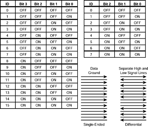
Note One of the major design criteria in the creation of SCSI-2 was backward compatibility with SCSI-1. In most cases, SCSI-2 devices will work with older SCSI-1 devices on a bus. This is not always practiced because older devices cannot support the SCSI-2 enhancements and faster transfer protocols. 6.3.2 SCSI AddressingEach device must have a unique target ID to enable the SCSI bus to distinguish the devices. For an 8-bit bus, a maximum of 8 targets is possible, using the 8 data channels on the bus. Narrow SCSI devices are numbered 0 through 7. For wide buses, the maximum number of target devices is 16. Wide SCSI devices are numbered 0 through 15. Wide devices that support 16 IDs use a 4-bit jumper block. The SCSI device ID settings are shown in Figure 6-6. Figure 6-6. SCSI device ID settings.
Note The host adapter is a SCSI device that requires an ID. Some older host adapters can be strict about device IDs and will only start from a hard drive if it is set to device ID 0. Newer hardware has corrected this limitation. The higher the SCSI target ID, the higher the priority of the device. In the event of arbitration between devices, the device that has the highest SCSI ID will win. Example Information on a disk device should be more readily accessible (has a higher priority) than data from a backup tape. Therefore, a Self-Monitoring Analysis and Reporting Technology (S.M.A.R.T.) disk controller should have a higher target ID number than the tape controller. This system has led to the unofficial standard of using SCSI ID 7 for the host adapter. Note On a Wide SCSI bus, the lower eight IDs have higher priorities than the higher eight IDs. This makes the priority order of target IDs on a Wide SCSI system 7, 6, 5, 4, 3, 2, 1, 0, 15, 14, 15, 12, 11, 10, 9, and 8. Note A Narrow SCSI device cannot communicate with a SCSI device with a target ID larger than seven. Do not move the target ID of the SCSI host adapter to a number higher than seven. 6.3.2.1 CONFIGURING SCSI IDSThe method of configuring the ID depends on the specific piece of hardware. Many devices use hardware switches, jumpers, or a rotary dial on the back of the device enclosure to set the device ID. More sophisticated devices, especially the more modern SCSI host adapters, use software utilities. Plug-and-play SCSI allows for automatic assignment of device IDs on the bus to eliminate simultaneous use of a single ID on multiple devices. SCA systems, introduced with SCSI-3, use a special single connector to provide power and data to each hard drive and to allow the controller to set the device ID of each drive. 6.3.2.2 SCSI DEVICE ID GUIDELINESThe SCSI device ID guidelines include the following:
Note HP restricts the number of devices on a bus because some wide controller implementations support only seven devices on a wide channel. However, wide SCSI generally accepts up to 15 devices in addition to the controller. 6.3.2.3 LOGICAL UNIT NUMBERSEach SCSI ID device can be broken down into logical unit numbers (LUNs). The number of LUNs available depends on the number of available data lines, as follows:
Each disk in a device can be addressed independently through LUNs (a four-disk CD jukebox could be assigned LUN 0 to 3). Example A CD-ROM storage system that contains six individual CD-ROM drives is addressed logically as a single SCSI device and requires only one SCSI ID. The individual CD-ROM drives are addressed using LUNs. Consequently, it is possible to daisy chain up to 7 (15 for Wide) CD-ROM expansion units (containing a total of 42 CD-ROM drives) on a single SCSI bus. 6.3.3 SCSI CommunicationWhen SCSI devices communicate on the bus, one device acts as an initiator and the other device acts as a target. The initiator is a SCSI device capable of starting an operation and is typically an adapter or controller in the host computer. The initiator starts an operation and is responsible for target selection and for providing commands and data. The target is a SCSI device that performs the operation. SCSI storage devices have a fixed role, usually as a target. Information transfer on the SCSI bus is allowed between only two SCSI devices at a time. The target manages the commands provided by the initiator and performs the operations. All activity on the SCSI bus occurs in one of eight SCSI bus phases. The bus phases determine the direction of the transfer and the type of information that is placed on the data lines. The first four phases are collectively known as the negotiation phase because they are used by a SCSI device to obtain permission to use the SCSI bus. The last four phases are collectively known as the information transfer phase because they are used to transfer data or control information. The information transfer phase does not have a specified order. Note The SCSI bus cannot be in more than one phase at a time. The following table describes the SCSI bus phases and their functions.
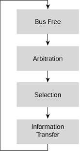
SCSI uses an arbitration or requesting technique to control the bus. Arbitration is a priority system that grants control of the SCSI bus to the highest priority SCSI device that is requesting use of the SCSI bus. With SCSI, a bus master priority is established as each device arbitrates for control of the bus. After an initiator recognizes that the bus is free, it asserts a bus-busy signal and its own ID on the bus. After the arbitration delay, the initiator checks the data bus and clears itself from arbitration if a higher ID device is on the bus. Information transfers on the data bus are asynchronous and conform to a request/acknowledgment handshake, followed by 1 byte of data. 6.3.4 SCSI Bus TransactionsCertain SCSI bus functions are assigned to the initiator and target. The initiator arbitrates for the SCSI bus and selects a target. The target requests the transfer of command, data, status, or other information on the data bus, and in some cases, the target arbitrates for the SCSI bus and reselects an initiator to continue an operation. This process is illustrated in Figure 6-7. Figure 6-7. SCSI bus transaction process.
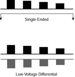
6.3.4.1 NEGOTIATIONNegotiation is the process in which the controller agrees on a transfer rate with each connected device during the initialization phase. During negotiation, the decision to operate in Fast-Wide mode during the data transfer phase is made on a drive-by-drive basis between the controller and drive during the command setup phase. ! Important The controller and drive negotiate individually for the highest data transfer speed they can handle. This is important if 8- and 16-bit SCSI devices share a bus. Do not disable negotiation, setup, or jumpers unless a SCSI device fails to respond during the negotiation phase. It is possible for a Fast SCSI controller to communicate with both Fast SCSI-2 hard drives and Fast-Wide SCSI-2 hard drives. A Fast-Wide SCSI-2 controller can be used with either type of hard drive. ! Important The maximum transfer rate between the SCSI controller and each disk drive on the bus is determined by the native protocol of the slowest device. 6.3.4.2 DISCONNECT AND RECONNECTWhen a SCSI device receives a request, it disconnects temporarily from the bus when it processes the data internally. The SCSI device reconnects with the bus after it has processed the request, which enables seven devices to operate simultaneously on a single bus. The data presented by the individual devices is then transferred across the bus in an interleaved mode. Connect and disconnect times are a function of the SCSI controller as well as the SCSI devices. The ability of the SCSI host and devices to disconnect rapidly from the SCSI bus enhances performance. Disconnect times are continually decreasing as technology progresses. 6.3.4.3 TAGGED COMMAND QUEUINGTagged command queuing (TCQ) enables a drive to receive many commands and perform those commands without involving the SCSI bus. This allows other devices to use the bus. The drive indicates when it has completed the commands, when its buffers are full, and when it is ready to transfer information. This technique increases the efficiency of a bus that can have only one target active at a time. A SCSI device that supports TCQ can accept up to 256 SCSI commands to optimize command execution. Example A hard drive accepts 10 write commands and 5 read commands, then sorts them to optimize head positioning. This increases throughput by almost 30% or more. A tag uniquely identifies each I/O request. The operating system uses the tag to see which I/O in the device driver queue is reported as complete by the device. An initiator can add or delete commands from the queue. When adding commands to the device queue, the initiator can specify a fixed order of execution or specify the next command to be executed. Otherwise, all commands are executed in the order received. Implementing TCQ is optional for SCSI-2. Modern SCSI devices, particularly magnetic drives, support TCQ, which allows the device to have multiple I/O requests outstanding at the same time. Because the device is intelligent, it can optimize operations, such as head positioning, based on its own request queue. Note On SCSI devices such as RAID arrays, the TCQ function takes advantage of the inherent parallelism of the device. Some operating systems also support presorting data to reduce head positioning, but in RAID systems, this type of presorting is optimized for access to the logical drive, not the physical drive. This can actually lead to an increase in head movements. Therefore, TCQ is essential at the hardware level. TCQ requires device driver support. TCQ belongs to the set of optional SCSI commands and is not supported by some drive manufacturers. If an unsupported drive is connected to the bus, TCQ must be disabled completely, which leads to degraded performance. Note All HP SCSI hard drives support TCQ. 6.3.4.4 ELECTRICAL SIGNALING SYSTEMSSignal integrity on the bus is always a concern. The longer the cables, the more problems there can potentially be with signal degradation or interference. The faster the bus runs, the more difficult it is to keep the signals clean. SCSI has defined two electrical signaling systems: single-ended SCSI and differential SCSI. Differential SCSI includes both high-voltage differential (HVD), and low-voltage differential (LVD). A comparison between these two electrical signaling systems is shown in Figure 6-8. Figure 6-8. SCSI electrical signaling systems.
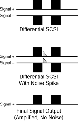
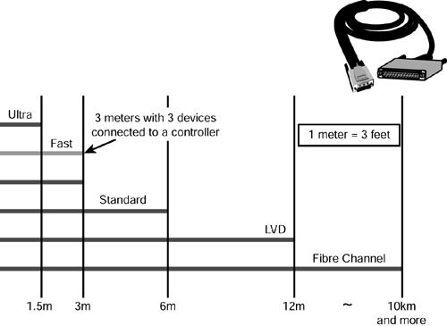
6.3.4.4.1 Single-Ended SCSIOn a single-ended interface, data travels over a single wire known as the signal line. There is a corresponding ground wire for the signal line. However, voltage is carried only on the signal line. A positive voltage is a 1 and ground voltage is a 0. Single-ended SCSI is the most common type of SCSI because it offers the most flexible and cost-effective solutions. However, the cable length of the bus is extremely limited. A single-ended SCSI bus uses signals that are either 5V or 0V and are relative to a common ground reference. A single ended 8-bit SCSI bus has approximately 25 ground lines, which are all tied to a single rail on all devices. The signals in the parallel signal lines can interfere with each other. Therefore, single-ended SCSI allows only short cables. HP uses only single-ended SCSI because this configuration uses inexpensive cabling and operates reliably when all the SCSI rules are observed. A standard single-ended bus has a maximum length of 6m. If the same bus is used with Fast SCSI devices, the maximum length allowed decreases to 3m. Fast SCSI means that on a narrow channel, instead of 5MB/s, the bus allows 10MB/s transfers. On a wide channel, it allows 20MB/s. Ultra SCSI and Ultra2 allow for 20MHz and 40MHz, respectively. Therefore, Ultra is 20MB/s on an 8-bit bus and 40MB/s on a 16-bit bus. For Fast-20, the maximum bus length is 1.5m, and for Fast-40, the maximum bus length is 12m. Note If some devices on the bus use Ultra SCSI or Ultra2 to communicate, the bus must adhere to the length restrictions for fast buses. 6.3.4.4.2 Differential SCSIDifferential SCSI uses a paired plus and minus signal level to reduce the effects of noise on the SCSI bus. Each signal is carried on a twisted pair of wires. A 1 is represented by a positive voltage on one wire and an equal but opposite negative voltage on another wire. A 0 is electrical ground, or zero voltage, on both wires. Any noise injected into the signal would be present in both a plus and minus state and would be canceled out. This concept is illustrated in Figure 6-9. Figure 6-9. How differential SCSI cancels noise.
Using two conductors per signal makes the signal more resilient and less likely to be corrupted, enabling the use of much longer cabling than single-ended SCSI. This does increase the cost, however. Conventional differential SCSI is now referred to as HVD. A differential SCSI bus has a maximum length of 25m. A single-ended Fast SCSI bus has a maximum length of 3m. Differential interfaces use a twisted-pair cable for every SCSI signal. The signal integrity is verified at the cable end before the data is passed to the drives, so it is used in external applications. Differential signals give a greater noise margin. Differential buses normally will be used for intercabinet connections. Because of the lower cost, single-ended SCSI typically is used for shorter buses. Example If the original signal is at 5V, then the other line has the inverse signal of 5V. The differences are amplified, and the difference between the two lines is 5V ( 5V) = 10V. The second line is subtracted from the first line because the difference is being used. A noise spike or other electrical noise on the lines would occur at the same time and at approximately the same amplitude. Example If a 1V noise spike occurred, then both lines would have the 1V spike at the same time. The difference is 1V 1V = 0V, and the spike is canceled out by the differential amplifier. This is called common-mode rejection because signals that are common, or in phase, are rejected. Transfer rate protocols are defined for potential use in each of these signaling systems. This does not mean that all of the different protocols are readily available in both single-ended and HVD SCSI. HVD SCSI is used far less often and is much more expensive. High-Voltage Differential A differential interface uses signal transmitters and receivers to drive the signal over longer distances and create greater noise immunity than single-ended buses. The signal is split into positive and negative components and transmitted over cable pairs. Five volts is carried on both wires. The signal is recombined at the receiving device. Greater noise immunity allows substantially longer SCSI cables of up to 25m, compared to 6m or less for single-ended devices. It also produces a faster data transfer rate. Differential and single-ended SCSI are not compatible on the same bus without an electronic device, such as a SCSI converter, to convert between differential and single-ended configuration. Warning Single-ended and HVD SCSI are incompatible at the electrical level. Do not mix single-ended and HVD SCSI devices on the same bus or physical damage to equipment could result. Low-Voltage Differential This interface uses 3.3V and differential modes of operation to increase cable length up to 12m, although using 80MB/s transfer effectively eliminates line noise. Therefore, this interface is both faster and more reliable than existing single-ended SCSI configurations. LVD was created to reduce costs associated with HVD. LVD SCSI is a technology that is the best choice in configurations in which Fibre Channel is too costly and single-ended SCSI is not viable because of its cable-length constraints. The lower voltage also means lower radiation of electromagnetic signals. Note Single-ended and LVD devices can be used on the same bus, but the entire SCSI bus will then run with single-ended speeds. 6.3.4.5 CABLESThe type of SCSI cable used depends on the protocol and configuration. Cable selection can be confusing because SCSI has a variety of protocols and configurations and differential and single-ended SCSI devices look identical. Figure 6-10 shows cable lengths that can be used with different SCSI standards. Figure 6-10. SCSI cable lengths.
Although single-ended cables are more common, both single-ended and differential cables share the following characteristics:
The SCSI bus width dictates the cable type, and the bus speed dictates the cable length. Faster SCSI buses that have more problems with signal corruption over longer distances are restricted to using shorter cables when using single-ended SCSI. Differential SCSI allows longer lengths regardless of speed. 6.3.4.5.1 Cabling ConsiderationsThe cables used for single-ended and HVD SCSI look the same. Verify the cable type before installation. Converters between single-ended and HVD SCSI are available. Single-ended and HVD SCSI signaling methods, device cabling, and electrical characteristics are not compatible, except with special adapters. Matching the type of devices used with a SCSI host adapter is important. HP has certified 4m (12-ft) cables in Fast, Fast-Wide, and Wide-Ultra rack solutions. Two-meter (6-ft) cables are certified for tower solutions. HP overcame the Fast SCSI and Ultra SCSI cable length restrictions by using specially designed expander chip technology. An expander chip is a device that joins independent SCSI bus cables, so the cables seem as a single SCSI bus to all attached devices. The expander chip technology allows the data signal to be powered at the same strength as the previous SCSI protocol, but allows the data bandwidth to function at the faster protocol. The result is that cables are qualified by HP to support a combination of 2m and 4m cable length and the faster data protocol from Wide-Ultra SCSI-3. The only cable with the 1.5m (4.5-ft) restriction is the daisy chain cable for the HP SCSI Storage Expander. 6.3.4.6 SCSI CONNECTORSThe table on the following page provides examples of SCSI connectors. Electrical signals travel across wires in a manner similar to physical waves traveling across a string. When the signals reach the end of the wire, the signals reflect and travel back across the wire. If this happens, the reflected signals interfere with the other data on the bus and cause signal loss and data corruption. To ensure that this does not happen, you must terminate each end of the SCSI bus. Special components are used to catch any signals that make it to the end of the bus and prevent them from reflecting. 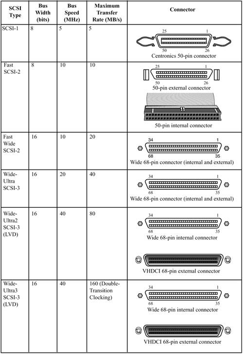 SCSI buses use two kinds of termination, which differ in the electrical circuitry used to terminate the bus:
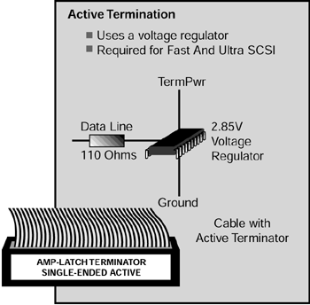
6.3.4.6.1 Terminator PowerTerminators need power to operate properly. On the SCSI bus, a line is dedicated to this purpose. TERMPWR is a 5V signal used to power the termination logic. Usually the controller delivers this voltage. Each device can provide its own terminator power through integrated terminator sockets. When using HP equipment, always set the TERMPWR jumper to TERMPWR = OFF. Note When a device supplying integrated terminator power to the SCSI bus line is intentionally or inadvertently powered off, the bus is no longer terminated. When external terminators are mixed with integrated terminators on the device, the system can be accidentally configured with terminators in locations other than the end of the bus or with terminators in addition to the required two per bus. This configuration causes system failures or errors. Initiators are devices that start actions on the bus and supply terminator power. All SCSI devices are allowed, but are not required, to supply terminator power. To allow for unpowered devices on a bus, the terminator power must be supplied to the bus through a diode, preventing a backflow of current to unpowered devices. The terminator power is usually fused. A blown fuse can lead to a nonfunctional bus. If multiple devices supply terminator power, a single blown fuse will not make the bus inoperable. External terminators sometimes have an LED indicator that shows whether terminator power is present. Newer designs sometimes use autorestoring fuses that reset themselves. Although there are four methods for terminating single-ended SCSI cables, the ANSI committee has approved only passive and active, and passive is no longer used on modern HP systems. Passive and active termination also require termination from both sides of the cable. In this rapidly changing area, better terminating techniques are discovered that improve overall signal quality and provide better grounding capability. Additionally, all signals not defined as RESERVERS, GROUND, or TERMPWR will be terminated. | ||||||||||||||||||||||
| < Day Day Up > |
EAN: 2147483647
Pages: 278
- Challenging the Unpredictable: Changeable Order Management Systems
- ERP System Acquisition: A Process Model and Results From an Austrian Survey
- Data Mining for Business Process Reengineering
- A Hybrid Clustering Technique to Improve Patient Data Quality
- Development of Interactive Web Sites to Enhance Police/Community Relations