7.4 Code-Aided Techniques
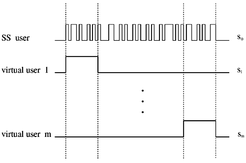
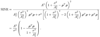
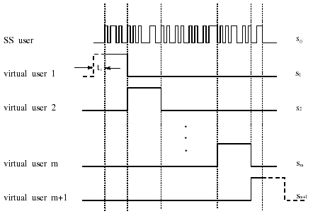
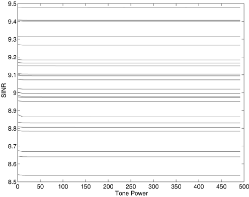
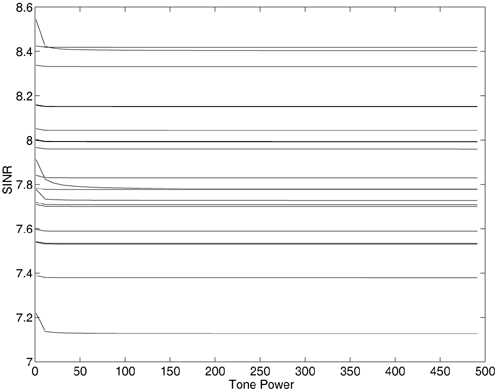
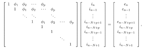
7.4 Code-Aided TechniquesIn preceding sections we discussed the use of linear predictive interference suppression methods, which make use of the spectral properties of the spread data signal. We also discussed improvement in these predictive methods by making use of a more accurate model for the spread-spectrum signal. In the latter situation, we considered in particular the first-order probability distribution of the data signal (i.e., binary valued) which led to the ACM filter and its adaptive transversal form. Further improvements in NBI suppression can be made by going beyond random modeling at the chip level and taking advantage of the fact that we must know the spreading code of at least one user of interest in order to begin data demodulation. Techniques for taking advantage of this are termed code-aided techniques , a term coined in [388]. This approach was first proposed in [381, 426] and has been explored further in several works, including [388 “390]. These works have been based primarily on detectors originally designed for linear multiuser detection. As noted in Section 2.2, in the context of multiuser detection, linear detectors operate by estimating the data sequence via linear model-fitting techniques and then quantizing the resulting estimates to get estimates of the data symbols themselves . Two of the principal such multiuser detection techniques are the zero-forcing detector, or decorrelator, and the linear MMSE detector. Recall that the decorrelator completely eliminates the multiple-access interference (MAI), with the attendant disadvantage of possibly enhancing the ambient noise, while the linear MMSE detector reduces the latter effect by minimizing the mean-square error between the linear estimate and the transmitted symbols. The linear MMSE detector has the further advantage of being more easily adapted than the decorrelator and it results in a lower bit-error rate under most practical circumstances [343, 386]. Although developed originally for the suppression of intersymbol interference and (later) MAI, these two methods can also be applied to the problem of suppressing NBI. This idea was first proposed in [381, 426] for the case in which the NBI signal is also a digital communications signal, but with a data rate much lower than the spread-spectrum chip rate. This digital NBI model finds applications, for example, in modeling the interference in multirate CDMA systems in which multiple spreading gains and multiple chip rates may be employed (e.g., [74, 333]). In [425], the decorrelator was employed to suppress the NBI in such cases, and comparison with even ideal predictive techniques showed significant performance gains from this method. The linear MMSE detector, in both fixed and adaptive forms, was proposed for suppression of digital NBI in [390], again resulting in significant performance gains over predictive techniques. The linear MMSE detector was explored further in [388, 389] for suppression of tonal and entropic narrowband interferers and for the joint suppression of NBI and MAI. 7.4.1 NBI Suppression via the Linear MMSE DetectorAs before, we begin by considering the case of (7.1) “(7.2) in which there is only a single spread-spectrum signal in the channel (i.e., K = 1) in addition to the NBI signal and white Gaussian noise. We again adopt the discrete-time model (7.5), and (without loss of generality) restrict attention to the observations in a single symbol interval, say the zeroth one: [0, T ]. It is convenient here to represent the corresponding samples in vector form: Equation 7.67 where for convenience we denote A Equation 7.68 i =[ i i 1 ... i N-1 ] T is a vector containing the NBI samples; and In this framework the linear MMSE detector has the form Equation 7.69 where Equation 7.70 As we have noted before, the motivation for this criterion is that we would like for the continuous estimator w T r of the symbol b to be as close to the symbol as possible in some sense before quantizing it. The MSE is a convenient and tractable measure of closeness for this purpose. Using (7.67), and the assumption that b , i , and n are mutually independent, (7.70) can be written as Equation 7.71 Taking the gradient of the MSE with respect to w and setting it to zero, we get Equation 7.72 Solving for w in (7.72), and using the matrix inversion lemma, we obtain the minimizing weights as Equation 7.73 A useful figure of merit for assessing the NBI suppression capability of the linear detector with weights w is the output signal-to-interference-plus-noise ratio, which is defined in this situation as Equation 7.74 Using (7.67), (7.73), and the assumption that b , i , and n are independent and zero mean, we have Equation 7.75 Equation 7.76 Substituting (7.75) and (7.76) into (7.74), the output SINR for the linear MMSE detector is then given by Equation 7.77 As noted previously, the NBI signal can be modeled in one of three basic ways: a tonal signal, an entropic narrowband stochastic process, or a digital data signal with data rate much lower than the spread-spectrum chip rate. We next analyze the performance of the linear MMSE detector against each of these three types of narrowband interference. 7.4.2 Tonal InterferenceFor mathematical convenience, we assume that the narrowband interference signal consists of m complex sinusoids of the form Equation 7.78 where P l and f l are the power and normalized frequency of the l th sinusoid, and the { F l } are independent random phases distributed uniformly on (0,2 p ). The covariance matrix R i of the multitone interference signal i can be represented as Equation 7.79 where Equation 7.80 Denote Equation 7.81 where Equation 7.82 Assuming that the spread-spectrum user has a random signature sequence, we next derive expressions for the expected values of the output SINR with respect to the random signature vector s , for several special cases. Case 1: m = 1. We have Equation 7.83 where we have used Equation 7.84 Therefore, when N is large, the energy of a strong interferer is almost completely suppressed by the linear MMSE detector. Case 2: m = 2. From (7.81) we have Equation 7.85 where Equation 7.86 Using (7.85), we have Equation 7.87 where Equation 7.88 where Equation 7.89 Substituting (4.55) and (7.89) into (7.86), we then have Equation 7.90 Again we see that for large N , the interfering energy is almost completely suppressed. In general, it is difficult to obtain an explicit expression for E {SINR m } for m > 2. However, for the special case when the { g l } are mutually orthogonal, a closed-form expression for E {SINR m } can easily be found. Case 3: Orthogonal { g l }. Assume that Equation 7.91 This condition is met, for example, when f l - f K is a multiple of 1/ N for all l Equation 7.92 The expected value of the output SINR with respect to the random signature vector s is Equation 7.93 where Figure 7.10. Numerical examples of multitone interference suppression in a CDMA system by the linear MMSE detector. The parameters are N = 31, A 2 = 1, and s 2 = 0.1. The interfering tones have the same power p l ranging from 1 to 500. Each curve in the plots corresponds to one set of (a) three-tone or (b) seven-tone frequencies { f l } randomly chosen. The SINRs are calculated by using (7.77). 7.4.3 Autoregressive InterferenceLet us assume that the NBI signal is modeled as a p th order AR process, where p << N : Equation 7.94 where { e n } is an i.i.d. Gaussian sequence with variance v 2 . Supposing that R i is positive definite, we first drive a closed-form expression for Equation 7.95 or, in compact form, Equation 7.96 where A is the matrix appearing on the left-hand side of (7.95), i N-p =[ i n , i n -1 , ..., i n-N+p +1 ] T , i p =[ i n-N+p , i n-N+p -1 , ..., i n-N +1 ] T , and e N-p =[ e n , e n -1 , ..., e n-N+p +1 ] T . Multiplying both sides of (7.96) by their transposes and taking expectations, we obtain Equation 7.97 that is, Equation 7.98 where Equation 7.99 Equation 7.100 Partition the N x N matrix A into the following four blocks: Equation 7.101 where A 11 is of dimension ( N - p ) x ( N - p ), and A 12 is of dimension ( N - p ) x p . Substituting (7.101) into (7.100), we can write Equation 7.102 Now most of the elements of Equation 7.103 where D k contains the ( N - k ) elements on the k th upper (lower) diagonal of Next we consider the output SINR of the linear MMSE detector when the interferer is an AR signal. For the sake of analytical tractability, and to stress the effectiveness of the MMSE detector against the narrowband AR interference (versus the background noise), we consider the output SINR when there is no background noise (i.e., s 2 Equation 7.104 Equation 7.105 where in (7.104), we have made the approximation that D K [ i ] = D K [ Equation 7.106 As will be seen in Section 7.5, this SINR value is the same as an SINR upper bound given by the nonlinear interpolator NBI suppression method in the absence of background noise. 7.4.4 Digital InterferenceNow let us consider a system with one spread-spectrum (SS) signal and one narrowband binary signal in an otherwise additive white Gaussian noise (AWGN) channel. We assume for now that the narrowband signal is synchronized with the SS signal. Furthermore, we assume a relationship between the data rates of the two users (i.e., m bits of the narrowband user occur for each bit of the SS user). (Given the typical data rates employed in many wireless systems, it is often reasonable to assume an integer relationship between the bit rates. Situations in which this is not true are considered in [57].) As shown in Fig. 7.11, the narrowband digital signal can be regarded as m virtual users, each with its virtual signature sequence. The first virtual user's signature sequence equals 1 during the first narrowband user's bit interval (i.e., a virtual chip interval) and zero everywhere else. Similarly, each other narrowband user's bit can be thought of as a signal arising from a virtual user with a signature sequence with only one nonzero entry. It is obvious from this construction that the signature waveforms of the virtual users are orthogonal to each other. However, in general, the k th virtual user has some cross-correlation with the spread-spectrum user. If we use r to denote the vectors formed by the cross- correlations , defined explicitly in (7.108), the cross-correlation matrix R of this virtual multiuser system has the following simple structure (note that the SS user is numbered 0, and the m virtual users are numbered from 1 to m ): Equation 7.107 Figure 7.11. Virtual CDMA system: synchronous case. We have assumed that the narrowband user had a faster data rate than the SS user (but this rate is still much slower than the chip rate). The opposite case can also hold, and our analysis applies to it as well, although we do not discuss that case explicitly. The covariance matrix of the system in that case has the same structure as (7.107). Let T be the bit duration of the SS user, so that T/m is the bit duration of the narrowband user. Similarly, let N be the processing gain of the SS signal, so that the chip interval has length T/N . By our assumption that the interferer is narrowband, we have N >> m . Let s(t) be the normalized signature waveform of the SS user [i.e., s(t) is zero outside the interval [0, T ] and has unity energy]. Similarly, let p(t) be the normalized bit waveform of the narrowband user [i.e., p(t) is zero outside the interval [0, T/m ] and has unity energy]. Then the normalized signature waveform of the k th virtual user is p k (t) = p(t “(k “1) T/m ). The cross-correlation vector mentioned earlier is r = [ r 1 r 2 ... r m ] T , where r k is the cross-correlation between the k th virtual user and the SS user, defined as Equation 7.108 where the inner product notation denotes We assume that the SS user and the narrowband user are sending digital data through the same channel characterized by AWGN with power spectral density s 2 . Let A I be the received amplitude of the narrowband signal and A be the received amplitude of the SS signal. We use the notation that the narrowband user data bits during the interval (0, T ) are d 1 , d 2 ,..., d m , and the SS bit is b . When the users are synchronous, it is sufficient to consider the one-shot version of the received signal: Equation 7.109 where n(t) is the white Gaussian noise with power spectral density s 2 . The linear MMSE detector for user 0 (i.e., the SS user) is characterized by the impulse response w Equation 7.110 A closed-form expression for w is given by [520] as Equation 7.111 where w T = [ w , w 1 , ..., w m ] is the first row of the matrix Equation 7.112 and A = diag { A , A I , ... A I }. Substituting (7.107) into (7.112), we have Equation 7.113 The following matrix identity can be easily verified , Equation 7.114 where g = 1 “ r T r / a b . Now on defining a = 1 + s 2 / A 2 and b = 1 + s 2 / A 1 2 , the first row of C in (7.113) is then given by Equation 7.115 Substituting (7.115) into (7.111) we get an expression for the linear MMSE detector for the SS user: Equation 7.116 Using (7.74), the SINR at the output of the linear MMSE detector w ( t ) becomes Equation 7.117 That is, the SINR is the ratio of the desired SS signal power to the sum of the powers due to narrowband interference and noise at the output of the filter w ( t ). Substituting (7.116) into (7.117), we obtain Equation 7.118 Figure 7.12 illustrates the virtual multiuser system for the asynchronous case. Let t be the fixed time lag between the spread-spectrum bit and the nearest previous start of a narrowband bit (i.e., 0 Figure 7.12. Virtual CDMA system: asynchronous case. |
EAN: 2147483647
Pages: 91


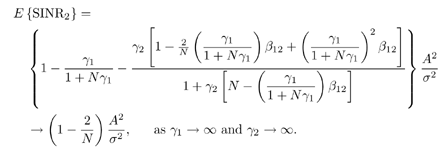
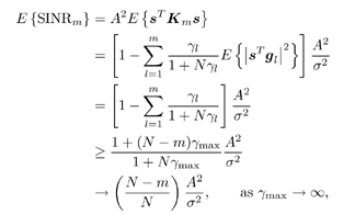
 K. Under this condition of orthogonality, it follows straightforwardly that

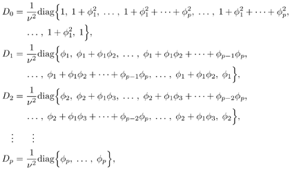
 0). Using (7.103), we have

 ], 0
], 0 

