VoIP Network Architectures
| One benefit of VoIP technology is that it allows networks to be built using either a centralized or a distributed architecture. Corporate business requirements dictate the architecture and functionality that is required. This section discusses centralized and distributed architectures and the gateway requirements to support these architectures in enterprise and service provider environments. Support for protocols, signaling capabilities, voice features, and voice applications is changing and growing quickly. You must have a good understanding of voice network architectures to know which business requirements each architecture addresses. Also, gateways play an important role in providing access to the right mix of functionality. You must understand the main features and functions required in enterprise and service provider environments to choose the appropriate gateway. Centralized Network ArchitecturesOne benefit of VoIP technology is that it works with centralized and distributed architectures. This flexibility allows companies to build networks characterized by both simplified management and endpoint innovation. It is important to understand the protocols that are used to achieve this type of VoIP network agility. The multisite WAN model with centralized call processing, as illustrated in Figure 5-2, consists of the following components:
Figure 5-2. Centralized Network Architectures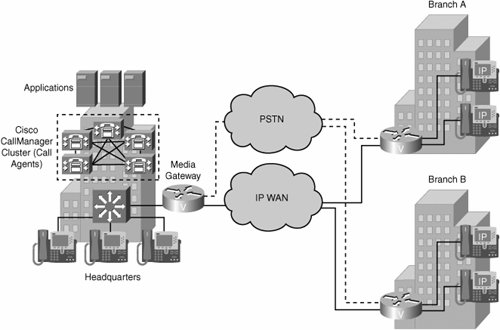 Centralized call-processing deployments typically offer the following characteristics:
A typical use for centralized architecture is a main site with many smaller remote sites. The remote sites are connected via a QoS-enabled WAN but do not require full features and functionality during a WAN outage. MGCP and Megaco/H.248 are the prevalent signaling protocols used in centralized architectures to control gateways and endpoints. Applications such as voice mail and IVR systems are typically centralized to reduce the overall cost of administration and maintenance. Cisco CallManager clusters can support up to 30,000 IP phones per cluster, providing for a scalable solution in enterprise environments. For even more scalability, clusters can be interconnected via intercluster trunks. CAC is administered by the Cisco CallManager cluster. CAC is critical in enterprise implementations that include WAN connections because these connections typically have limited bandwidth that is shared between voice and data users. Control must be established over the number of calls that can flow concurrently across the WAN at any given time so that as the call volume grows, overall call quality does not diminish. One disadvantage of implementing a centralized architecture is that if the WAN connection fails between the remote site and the central site that houses Cisco CallManager, no further voice calls can be processed by the remote site. Additional steps need to be taken to ensure that data and voice services at the remote sites remain available. One option is to implement redundant WAN links between the remote sites and the central site. In many cases, this solution is not financially feasible. Alternatively, Survivable Remote Site Telephony (SRST) provides high availability for voice services. SRST provides a subset of the call-processing capabilities within the remote-office gateway. It also enhances the IP phones with the ability to "re-home" to the call-processing functions in the local gateway if a WAN failure is detected. This feature allows the remote site to continue to provide voice connectivity in the absence of the WAN link. Most centralized VoIP architectures use MGCP or Megaco/H.248 protocols. You can also build session initiation protocol (SIP) or H.323 networks in a centralized fashion. This is done using back-to-back user agents (B2BUAs) or gatekeeper-routed call signaling (GKRCS), respectively. Figure 5-2 shows a typical centralized call-processing deployment, with a Cisco CallManager cluster acting as the call agent at the central site and an IP WAN with QoS enabled to connect all the sites. The remote sites rely on the centralized Cisco CallManager cluster to handle their call processing but have local voice-enabled routers to perform the voice-gateway translations for media streams. Each remote site connects locally to the PSTN. Long-distance (LD) service might be provided from the head office or through each local PSTN connection. H.323 Distributed Network ArchitecturesThe multisite WAN architecture with distributed call processing consists of multiple independent sites. Each site has its own call-processing agent, which is connected to an IP WAN that carries voice traffic between the distributed sites. Each site in the distributed call-processing architecture using H.323 can be comprised of one of the following:
Figure 5-3 provides an example of a distributed call-processing architecture. Notice, in the figure, that each site contains its own call-processing agents (in the form of CallManager clusters). This type of call-processing approach has the following characteristics:
Figure 5-3. Distributed Network Architectures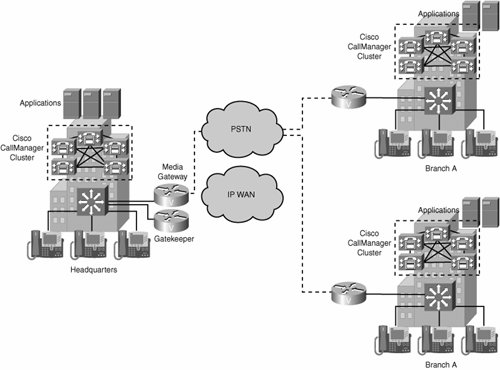 Multisite distributed call processing allows each site to be completely self-contained. The IP WAN in this model does not carry call-control signaling for intranet and off-net calls because each site has its own Cisco CallManager cluster. Typically, the PSTN serves as a backup connection between the sites in case the IP WAN connection fails or does not have any more bandwidth available. Distributed architectures are associated with H.323 and SIP protocols. These protocols allow network intelligence to be distributed between endpoints and call control devices. Intelligence in this instance refers to any aspect of call handling including the following:
The endpoints can be VoIP gateways, IP phones, media servers, or any device that can initiate and terminate an H.323 VoIP call. The call control devices are called gatekeepers (GKs) in an H.323 network. In an enterprise environment where many gatekeepers are required, a second level of hierarchy is achieved through the use of directory gatekeepers (DGKs). Directory gatekeepers provide summarization capabilities for multiple configured gatekeepers. The multisite WAN architecture with distributed call processing consists of the following components:
Few implementations of call control are totally distributed. Although H.323 and SIP operate in a purely distributed mode, for scalability reasons both are most often deployed with common control components that give endpoints many of the advantages of a centralized call control environment. As a result, these implementations also inherit many of the disadvantages of centralized call control. SIP Distributed Network ArchitecturesThe rapid evolution of voice and data technology is significantly changing the business environment. The introduction of services such as instant messaging, integrated voice and e-mail, and follow-me services has contributed to a work environment where employees can communicate much more efficiently, thus increasing productivity. To meet the demands of the changing business environment, businesses are beginning to deploy converged voice-and-data networks based on SIP. SIP was originally defined in 1999 by the Internet Engineering Task Force (IETF) in RFC 2543. SIP is the IETF standard for multimedia conferencing over IP, and SIP is an ASCII-based, application-layer control protocol that can be used to establish, maintain, and terminate calls between two or more endpoints. Service development in the SIP environment is made easier because of its use of, and similarity to, Internet technologies such as HTTP, Domain Name System (DNS), and addressing in the form of e-mail addresses. SIP enables the integration of traditional voice services with web-based data services, including self-based provisioning, instant messaging, presence, and mobility services. A SIP-based network is made up of several components, as depicted in Figure 5-4, including:
Figure 5-4. SIP Network Components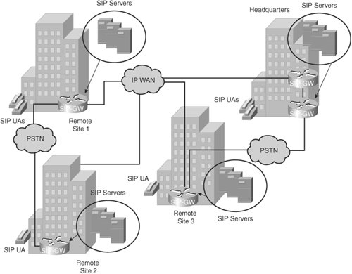 Additionally, SIP provides the following capabilities:
As a protocol used in a distributed architecture, SIP allows companies to build large networks that are scalable, resilient, and redundant. The SIP protocol provides mechanisms for interconnecting with other VoIP networks and for adding intelligence and new features on either the endpoints or the SIP proxy or redirect servers. Comparing Network ArchitecturesBoth the centralized and distributed models have advantages and disadvantages. Features that are considered advantages of one type of call control model might be disadvantages of the other type. The main differences between the two models are in the following areas:
Because the centralized model is more sensitive to IP WAN outages, a centralized model design mandates the implementation of survivability and load management strategies. Few implementations of call control are totally distributed. For example, H.323 and SIP operate in a purely distributed mode, but for scalability reasons, both are most often deployed with common control components that give endpoints many of the advantages of a centralized call control environment. Unfortunately, these implementations also inherit many of the disadvantages of centralized call control. Simple Multisite IP Telephony NetworkTo help solidify the concepts of the various call-processing models, consider a case study company, Span Engineering LLC. Span Engineering LLC is migrating to a Cisco IP telephony solution. It has three sites in the United States and a fourth site in Brazil. Figure 5-5 shows the distributed architecture implemented by Span Engineering. Notice in the figure that Post, Telephone, and Telegraph (PTT) is the international term for PSTN. Also, the term LD refers to a long-distance network. Figure 5-5. Distributed Architecture: Span Engineering Case Study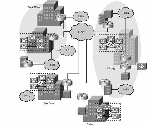 Span Engineering is a company based in the United States, with headquarters in Chicago and branches in Dallas and on the west coast of the United States. It has recently expanded internationally to Sao Paulo, Brazil. The plan for migrating to Cisco IP telephony includes eliminating all PBXs and migrating to full VoIP in the near future. The overall deployment model used by Span Engineering is multisite distributed and contains both centralized and single-site locations:
Interconnecting VoIP ProtocolsJust as companies choose various protocols for their data networks based on business and technical requirements, they also need to choose one or more protocols for their VoIP requirements. In an environment where more than one VoIP protocol is present, companies must support the interconnection between the differing VoIP protocols. Choices for interconnecting the segments that use differing VoIP protocols typically fall into one of the following three categories:
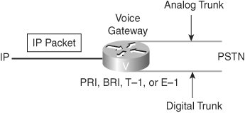
Understanding GatewaysA gateway is a device that translates one type of signal to a different type of signal. There are different types of gateways, including the voice gateway, as illustrated in Figure 5-6. Figure 5-6. Gateway Interfaces A voice gateway is a router or switch that converts IP voice packets to analog or digital signals that are understood by TDM trunks or stations. Gateways are used in several situations (for example, to connect the PSTN, a PBX, or a key system to a VoIP network). In Figure 5-6, the voice-enabled router (that is, the voice gateway) examines the incoming IP packet to determine whether it is a voice packet and determine the packet's destination. Based on information inside the voice packet, the router translates the digitized signal or voice into the appropriate analog or digital signal to be sent to the PSTN. For a call coming from the PSTN, the gateway interprets the dialed digits and determines the IP destination for the call. Guidelines for Selecting an Appropriate GatewayUnderstanding gateways and being able to select the correct gateway out of numerous gateway options is challenging. Factors to consider include the protocols that are supported, the density and types of interfaces on the gateway, and the features that are required. Knowing the requirements will guide you to the correct solution. One criterion involves defining the type of site that the gateway supports. Is it a small office/home office (SOHO), branch office, enterprise campus environment, or service provider? Each type of site has its own set of requirements. A key objective is to identify the number and type of voice interfaces that are necessary and to verify the protocol support. Are supplementary services supported? Which CODECs must be supported? Is fax relay necessary? Many of these functions are features of specific Cisco IOS software releases. Identification of the proper IOS software release necessary to support the features is critical. Another key consideration is whether the gateway is acting as a gateway only or needs to combine the functions of gateway and router within one device. This will point to a specific set of hardware and software. When planning gateways for placement in other countries, verify that the device meets the government standards for PSTN connection in that country. If the device supports encryption capabilities, verify the legality of export to the destination country. For example, consider a network where the requirements are to support Foreign Exchange Station (FXS) and E&M connections. The trunk is to be a T1 PRI from the PBX. In this case, a suitable choice would be a Cisco 3745 Multiservice Access Router with a two-slot voice network module (VNM), 1 FXS voice interface card (VIC), 1 E&M VIC, and a High Density Voice (HDV) module. Enterprise Central and Remote Site Gateway Interconnection RequirementsAs IP telephony services become a standard in the corporate setting, a broad mix of requirements surface in the enterprise environment. The IP telephony deployment is typically initiated by connecting to the PSTN to manage off-net calls while using a Cisco CallManager infrastructure to manage on-net calls. Table 5-3 shows example questions that you might ask to determine the requirements for gateway interconnections.
At the central site, several specific issues need addressing. These issues include:
Service Provider Gateway Interconnection RequirementsService providers must provide a level of service that meets or exceeds PSTN standards. The gateways that service providers implement must offer reliable, high-volume voice traffic with acceptable levels of latency and jitter. The following functions address those requirements:
Consider a scenario where an IP telephony service provider needs to upgrade its existing gateway platforms because of business growth. The service provider sells a managed IP telephony service to small- and medium-sized businesses and provides connections to many different low-cost, long-distance carriers. Their issues are call quality over the IP network. Delay and jitter need to be controlled. Service providers must also consider scalability and the ability to provide differentiated levels of service through QoS. They also need connectivity to the SS7 networks of long-distance carriers to reduce costs. Finally, the service provider needs to consider the overall cost of implementation. SS7 capabilities and a redundant design enable the service provider to deliver a reliable level of service. Practice Scenarios: Network ArchitectureThroughout this chapter, practice scenarios will help reinforce what you have learned. In this scenario, Span Engineering is assessing VoIP network architectures and reviewing components and functionality associated with each type of architecture. Your task is to view each scenario and determine the network architecture type and the protocols that are commonly used in support of the network architecture. Practice Scenario 1: Network Architecture and Protocol SelectionThe network shown in Figure 5-7 has the following characteristics:
Figure 5-7. Practice Scenario 1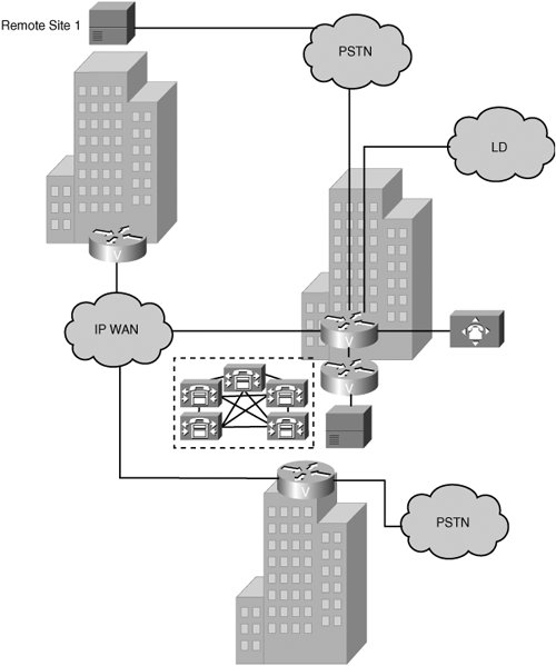 Based on the figure and on the preceding characteristics, identify the network architecture type and protocols that are commonly used to support that architecture. Network architecture: ____________________________ Protocols: _____________________________________ Practice Scenario 2: Network Architecture and Protocol SelectionThe network shown in Figure 5-8 has the following characteristics:
Figure 5-8. Practice Scenario 2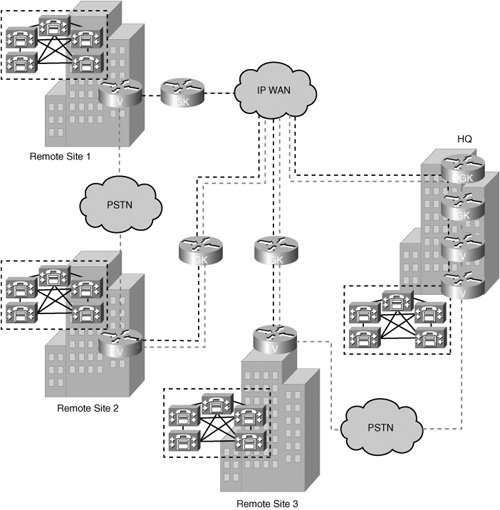 Based on the figure and on the preceding characteristics, identify the network architecture type and protocols that are commonly used to support that architecture. Network architecture: ____________________________ Protocols: _____________________________________ Practice Scenarios 1 and 2: SolutionsScenario 1:
Scenario 2:
|
EAN: 2147483647
Pages: 111