| Flash provides separate tools for drawing ovals, rectangles, and polygons or stars. The tools work similarly; all can draw a shape as an outline (just a stroke) or as a solid object (a fill). You can also create a geometric shape with a fill and a stroke simultaneously. To create geometric outlines 1. | In the Tools panel, select a geometric-shape toolfor example, the oval tool (Figure 2.25).
Figure 2.25. The Tools panel with the oval tool selected. 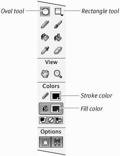
| 2. | In the Colors section of the Tools panel, click the paint-bucket icon to select the Fill Color control.
| 3. | In the Colors section of the Tools panel, select No Color (Figure 2.26).
Figure 2.26. When the Fill Color control is selected in the Colors section of the Tools panel, clicking the No Color button allows whatever tool you select to create a shape with no fill. 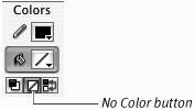
This setting enables the tool to draw outlines without a fill.
| 4. | Use the current stroke color and line weight, or select new ones (see "Setting Stroke Attributes," earlier in this chapter).
| 5. | Move the pointer over the Stage.
The pointer turns into a crosshair.
| 6. | Click and drag to create the geometric shape (Figure 2.27).
Figure 2.27. Click the Stage and drag to create an oval. You see a preview outline of your shape (top). Release the mouse button, and Flash creates an oval outline using the current color, thickness, and style settings. In this case, the oval tool is set to black stroke color, no fill, dashed stroke style, and a stroke height of 1 point (bottom). 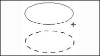
Flash previews the shape as you drag.
| 7. | Release the mouse button.
Flash draws the geometric shape as an outline.
|
 Tips Tips
Flash provides a line tool for drawing simple straight lines (strokes). To use the line tool, select it in the Tools panel and set its stroke attributes; with the line-tool pointer (a cross hair) active, click and drag on the Stage. You see a preview line as you drag. Flash creates the finished line, with the correct attributes, when you release the mouse button. To draw a perfect circle (or square), hold down the Shift key while you draw with the oval or rectangle tool. To make ovals (or rectangles) grow outward from the center point as you draw, position the pointer where you want the center of the shape to be; hold down the Alt key (Windows) or Option key (Mac) as you drag. Shapes drawn with the polystar tool always grow from the center. There are other ways to set geometric tools to draw just outlines. Click the Tools panel's Fill Color control directly on the color chip. A pop-up set of fill swatches opens. Now, click the No Color button near the top-right corner of the swatch pop-up. You can also use the Mixer panel: Select the Fill Color control, and then choose None from the Type menu.
Shapely Terminology The question of what to call the graphic elements created with Flash's drawing tools has always been a bit of a stumper, and the addition of Object Drawing mode makes it more perplexing. The general term shape might apply to the form of the element (round versus rectangular), or it might be used to distinguish something created in Merge Drawing mode from something created in Object Drawing mode. The term object has a specific meaning in ActionScript (see Chapter 7). To avoid confusion, here's how this book will talk about these elements. A shape is any stroke and/or fill created with Flash's drawing tools. A drawing-object is a shape created in Object Drawing mode or by using the Modify > Combine Objects command (see Chapter 5). A merge-shape (or raw shape) is a shape created in Merge Drawing mode. A grouped shape (or group) is a set of shapes that have been combined to act as a unit via Flash's Group command (see Chapter 5). The term graphic-object refers to drawing-objects, groups, and symbols. A graphic-object is a container that holds shapes; each type of graphic-object has specific rules that govern its behavior, for example, controlling how its contents interact with other graphic elements. (The word graphic here distinguishes these items from ActionScript objects.) |
To create geometric fills 1. | In the Tools panel, select a geometric-shape toolfor example, the rectangle (Figure 2.28).
Figure 2.28. When you select the rectangle tool in the Tools panel, the Round Rectangle modifier appears in the Options section. This setting gives you more control in creating rectangles with blunt corners. 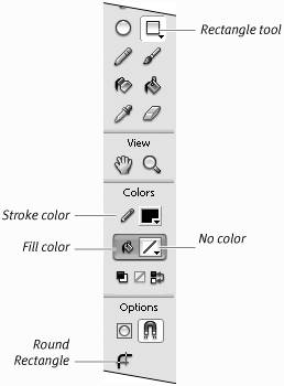
| 2. | To set the tool to create just a fill, in the Colors section of the Tools panel, do the following,
- Click the pencil icon to activate the Stroke Color control.
- Click the No Color button.
Flash enables the selected tool to draw fills without outlines.
| 3. | Select a fill color (see "Setting Fill Attributes," earlier in this chapter).
| 4. | Move the pointer over the Stage.
The pointer changes to a crosshair.
| 5. | Click and drag to create the geometric fill.
Flash previews the shape as you drag (Figure 2.29).
Figure 2.29. As you drag the rectangle tool, Flash creates an outline preview of a rectangle (left). To complete the fill shape, release the mouse button (right). 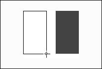
| 6. | Release the mouse button.
Flash draws a geometric fill, using the currently selected fill color.
|
Tips In "Setting Stroke Attributes," earlier in this chapter, you learned to use the Join setting in the Properties tab of the Property inspector to make line segments connect with mitered, beveled, or rounded corners. The rectangle tool can override that Join setting. Select the rectangle tool; in the Options section of the Tools panel, click the Round Rectangle button; and enter a value in the Corner Radius field of the Rectangle Settings dialog (Figure 2.30). With a 0 setting, the rectangle tool uses the Join setting; at higher settings, the tool creates rounded corners (the higher the setting, the more rounded the corners). Figure 2.30. Enter a value of 0 in the Corner radius field of the Rectangle Settings dialog to create a rectangle that uses the Join property you've set in the Properties tab of the Property inspector. Enter a larger value to round the corners of your rectangle precisely. 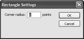 To reset the rectangle tool's corner radius to 0 quickly, Shift-double-click the rectangle tool or Shift-click the Round Rectangle button. You can change a rectangle's corner radius as you draw. Drag on the Stage with the rectangle tool to create your shape. Before releasing the mouse button, press the up-arrow key to reduce the corner-radius value; press the down-arrow key to increase it. The preview rectangle changes interactively as you press the arrow keys. Release the mouse button to complete your shape. You can create polygons and star shapes with the polystar tool (choose it from the rectangle tool's submenu in the Tools panel). To set the number of sides in the polygon and to switch from polygons to stars, you must enter tool settings via the PolyStar Tool Properties tab of the Property inspector. With the polystar tool selected, click the Options button in the Properties tab of the Property inspector. The Tool Settings dialog appears. Enter values for the number of sides and how sharp the star points are, and then click OK to close the dialog. You can draw precision ovals and rectangles by using the Oval Settings and Rectangle Settings dialogs. To access this feature, select the oval or rectangle tool. Option-click (Mac) or Alt-click (Windows) the Stage. The appropriate settings dialog appears. Enter values for your shape's height and width. These values describe the height and width of the rectangle or the bounding box that contains the oval. Select the Draw from Center check box to place your shape's center at the spot you clicked; deselect the check box to place the top-left corner of the shape, or bounding box, at the spot you clicked.
|