| A line has three main attributes: color, thickness (also known as weight or, in Flash, stroke height), and style. You can set all three in the Properties tab of the Property inspector for any tool that creates strokes (the line, pen, oval, rectangle, polystar, pencil, and ink-bottle tools). The Properties tab of the Property inspector also lets you control the way the ends of lines (caps) look and the way lines connect (joins). To set stroke properties 1. | With the Properties tab of the Property inspector open, in the Tools panel, choose a tool that creates strokes (line, pen, oval, rectangle, polystar, pencil, or ink bottle).
The Properties tab of the Property inspector for the selected tool appears, displaying the current settings for strokes.
| 2. | In the Properties tab of the Property inspector, click the Stroke Color control.
The pointer changes to an eyedropper, and a set of swatches appears (Figure 2.19).
Figure 2.19. Clicking the Stroke Color control in the Properties tab of the Property inspector opens a set of color swatches and provides an eyedropper pointer for selecting a new color. 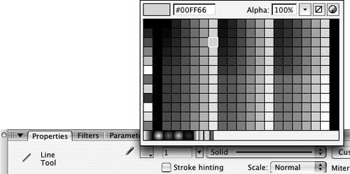
| 3. | Select a stroke color.
| 4. | To set the stroke's weight, in the stroke-height field, enter a number between 0.25 and 200, or drag the slider next to the stroke-height field (Figure 2.20).
Figure 2.20. Entering a new value in the stroke-height field sets the thickness for strokes created by tools that draw strokes. 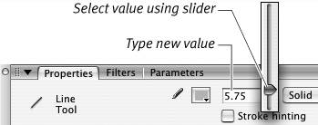
| 5. | To set the stroke's style, from the stroke-style pop-up menu (Figure 2.21), select a style.
Figure 2.21. Choose a stroke style from the pop-up menu in the Line Tool Properties tab of the Property inspector. 
There are seven styles to choose from: hairline, solid, dashed, dotted, ragged, stippled, and hatched.
A graphic representation of your selected style appears in the stroke-style menu.
| 6. | To set how the stroke ends, from the Cap pop-up menu, choose a cap style.
None ends the stroke exactly where you stop drawing it. Round extends the stroke by half the current stroke height, creating a rounded end. Square extends the stroke by half the current stroke height, creating a square end (Figure 2.22). Figure 2.22. Set a Cap style in the Properties tab of the Property inspector to control the look of the ends of lines. None keeps the line's original length and makes the end flat, Round extends and rounds the line's end, and Square extends and squares off the end. 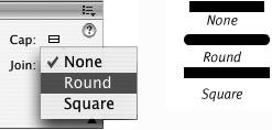
| 7. | To set the way strokes intersect, click the Join pop-up menu.
Miter creates a sharp point at the intersection of two strokes. Round creates a slightly curved intersection Bevel creates a slightly flattened intersection (Figure 2.23). Figure 2.23. Set a join style in the Properties tab of the Property inspector to control the way lines connect. Miter makes a clean pointed corner, Round makes a rounded corner, and Bevel slices a flat piece off the corner. 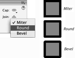
Flash uses all the settings currently active in the Properties tab of the Property inspector any time you choose a tool that creates strokes.
|
 Tips Tips
Use the three buttons at the bottom of the Tools panel's Colors section to set basic stroke (and fill) colors quickly. Clicking the leftmost button of the trio sets the stroke color to black (and the fill color to white). Clicking the rightmost button makes the current stroke and fill colors change places. (Clicking the middle button sets the fill or stroke to No Color when you use the oval, rectangle, and polystar tools.) In Flash, the hairline setting is considered to be a stroke style, not a stroke height. (Use the stroke-style pop-up menu to get the hairline setting.) In symbols, hairlines don't change thickness when you resize the symbol. Other lines in symbols grow thicker or thinner as you scale them up or down. (To learn about symbols, see Chapter 7.) To constrain the way strokes scale in your published movie, with a stroke (or stroke-creating tool) selected, choose a setting from the Scale menu in the Properties tab of the Property inspector. In the default (Normal) mode, a 1-pixel stroke becomes a 2-pixel stroke if your final movie gets enlarged to 200 percent. To prevent a selected stroke from scaling at all, choose None. To allow the stroke to scale in one direction only, choose Horizontal or Vertical. Click the Stroke hinting check box in the Properties tab of the Property inspector to ensure crisp lines on the strokes in your final output. Without it, lines can sometimes appear slightly blurry on some monitors. You can modify Flash's stroke styles. You might, for example, want larger dots in the dotted line or bigger spaces in the dashed line. In the (Line Tool) Properties tab of the Property inspector, select the style you want to modify, and then click the Custom button. The Stroke Style dialog appears, in which you can assign new settings. Click OK to close the dialog and confirm the settings. Those settings continue in force for that style until you change them or end the work session. You can also set stroke color in the Tools panel or Color Mixer panel. In either panel, click the Stroke Color control, and select a color as described in "Setting Fill Attributes," earlier in this chapter.
Merge Drawing vs. Object Drawing Flash 8 adds a new facet to the way you create graphic elements: there are now two models (or modes) for creating strokes and fills. In Merge Drawing mode, the strokes and fills you create are raw shapes (just as they were in previous versions of Flash). Raw shapes are ready for editing directly on the Stage; raw shapes on a single layer interact with one another, dividing and replacing strokes and fills that overlap or intersect (you'll learn more about how shapes interact in Chapter 5). In Object Drawing mode, the strokes and fills you create are still directly editable on the Stage, but they don't interact with other shapes on the same layer. To anyone who's used a previous version of Flash, these shapes may seem a little unpredictable. In some ways, shapes created in Object Drawing mode act as if they were isolated on a separate layer or protected using the Group command (you'll learn more about working with grouped shapes in Chapter 5 and about shapes on separate layers in Chapter 6). But shapes created in Object Drawing mode can be modified directly on the Stage (see Chapter 4), whereas grouped objects can't. In fact Object Drawing mode creates a whole new type of creature. Flash's default mode for drawing tools is Merge Drawing. To turn on Object Drawing mode, select a tool that creates strokes and/or fills, and then click the Object Drawing button in the Options section of the Tools panel (Figure 2.24). Once you activate Object Drawing mode for any tool, all tools that create strokes and fills are set to Object Drawing mode. To return to Merge Drawing mode, you must click the Object Drawing button again to deselect Object Drawing mode (or press J on the keyboard to toggle between Merge Drawing and Object Drawing). Whatever Merge/Object Drawing setting is active when you end a work session will be active the next time you open Flash. Figure 2.24. You can set the drawing tools to create shapes that don't interact with other shapes on the same layer. Select Object Drawing mode in the Options section of the Tools panel. 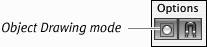
For many tasks, you'll see no difference between working with shapes created in Merge Drawing mode and shapes created in Object Drawing mode; in some tasks, however, the difference is crucial. For the exercises in this book, unless otherwise noted, you can use either drawing mode when creating shapes. |
|