Parameters of Audio Effects
Each audio effect has a set of parameters that you can change to alter the way the effect processes sound. The Rumpus 3D SFX sample maps each of these parameters to a control in the Change Special Effect Settings window to enable you to easily adjust the value so you can hear the result during playback. The following sections discuss the parameters for each effect, and provide some relevant background information.
Time Domain Effects
The following sections describe the time domain effects and their parameters:
-
Echo
-
Reverb
-
Chorus
-
Flanger
Echo Effect
It makes sense to begin the discussion of time domain effects with the echo effect because it is the most basic of the time domain effects. In its simplest form, the echo effect is like shouting into a canyon: the original sound occurs and, at some time in the future, it repeats (see Plate 3). When it repeats, the echo is perceived as being a completely separate instance of the sound.
Of course, this effect isn t unique to canyons. An empty soccer stadium or even an empty city street might give this effect. A large reflective surface must be far enough away from the source so that the sound takes a perceptible amount of time to travel to the surface and then reflect directly back to the listener.
The echo effect exposes the following parameters:
-
Left delay and right delay
-
Wet/dry mix
-
Feedback
-
Pan delay
Left Delay and Right Delay Parameters
The term delay refers to the time elapsed between when the original sound occurs and when the effect occurs. Delay is measured in milliseconds (ms). Sound travels through air at a rate of 1130 feet per second (at sea level when the temperature is 59 degrees Fahrenheit). This means that you can assume a delay of about 1 ms per foot of sound propagation. For example, to simulate an echo from a stadium wall 250 feet away, you could use a delay time of 565 ms (282.5 ms to the wall plus 282.5 ms from the wall).
The DirectSound echo effect is actually a stereo effect ” you can adjust the delay value separately for the left and right audio channels. This can be particularly useful to create a more realistic sense of space by using a slightly different delay time for each channel, which more closely approximates the way an echo would arrive at the listening position in the physical world.
Wet/Dry Mix Parameter
When discussing audio effects, the term dry always refers to the original signal, and the term wet always refers to the processed signal. For the echo effect, the wet/dry mix parameter enables you to adjust the balance between the volume of the original signal and the volume of the echo. This is useful because in the physical world, echoes always occur at a decreased volume relative to the original sound, the natural result of the sound wave traveling some distance to and from the reflective surface. The wave loses energy as it travels through air, and when the sound reflects off a surface, some energy is actually absorbed by the surface. How much energy is lost in this process varies by a number of factors, not the least of which is the material of which the reflective surface is made.
The wet/dry mix ( fWetDryMix ) parameter actually represents the percentage of processed signal in the final output. For example, a value of 30 means that 30 percent of the output signal is echo and 70 percent of the output signal is the original input signal. Figure 5.3 shows how signals are mixed by the DirectSound when you specify a value for the wet/dry mix parameter.

Figure 5.3: Block diagram of wet/dry mix functionality.
Feedback Parameter
When you see the term feedback , you might be inclined to think of the annoying squeal that happens when a performer points a microphone toward a speaker. Happily, the feedback parameter creates no such effect. Rather, this parameter mixes some of the processed signal back into the input buffer for the effect. The result is one of echoes creating echoes in a trailing, repetitive manner. Used carefully , feedback can make the canyon effect even more realistic. Lots of feedback can even make for an eerie, outer space-like effect.
The feedback ( fFeedback ) parameter represents the percentage of processed signal mixed back into the input. Figure 5.4 show how DirectSound feeds the output signal back into the input when you specify a value for the feedback parameter.
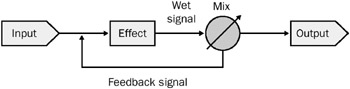
Figure 5.4: Block diagram of feedback functionality.
Pan Delay Parameter
The pan delay ( lPanDelay ) parameter enables you to specify whether the left delay and right delay values alternate, or swap, with each successive echo. If you create an effect with vastly different values for left delay and right delay, the pan delay effect can create a sense of motion as the echoes seem to move from speaker to speaker.
Reverb Effect
Reverb is a commonly used effect because enclosed spaces are always reverberant to some degree. This means that reverb is something people are accustomed to hearing as a natural occurrence, and when it is missing, sounds can seem quite unnatural . In the music industry, reverb is used extensively to enhance the sounds of vocalists and musical instruments because, used judiciously, it can add a sense of spaciousness and even help to gloss over flaws in the performance.
The reverb effect sounds more like a gymnasium or concert hall than like a canyon. The echoes that create this effect are not perceived as discrete events; they blend together to create an effect that builds quickly and then slowly fades away. It is the way that this effect waxes and wanes that gives each space its unique characteristics. The parameters enable you to adjust this behavior somewhat to create the space you desire .
There are two ways to create the reverb effect using DirectSound:
-
Waves reverb ( DSFXWavesReverb )
-
Environmental reverb ( DSFXI3DL2Reverb )
Waves Reverb
The Rumpus 3D SFX sample uses this type of reverb effect, which enables you to adjust the following parameters:
-
Reverb time
-
Reverb mix
-
High-frequency reverb time ratio
-
Input gain
Reverb Time Parameter
The reverb time ( fReverbTime ) parameter enables you to specify, in milliseconds, the amount of time it takes for the reverberation to fade by 60 dB after the input signal has ceased. This time is often referred to as the decay time. You can use this parameter to adjust the apparent size and composition of the space you are creating. Longer reverb times correspond to larger, more reverberant spaces.
Reverb Mix Parameter
Once again, imagine you are standing in a gymnasium. Imagine that you are standing at the foul line on the basketball court , and your friend is standing on the opposite foul line, facing you. Your friend shouts to you. What you hear is a mixture of direct sound, which arrives in a straight path from your friend s mouth to your ears, and reverberant sound, which arrives in a myriad of reflections. In fact, if your friend faces the other way, you hear only reverberant sound.
Now imagine that you and your friend are both standing at center court, having a conversation. What you hear is still a mixture of direct sound and reverberation, but now the vast majority of that sound comes directly from your friend s mouth to your ears.
The reverb mix ( fReverbMix ) parameter enables you to adjust this balance between direct and reflected sound. This can help you to simulate the placement of the listener in the space relative to the source of the sound. The parameter value is specified in decibels below maximum level, which means the value is always zero or some negative number. At zero, the output signal is 100 percent processed, at -96 dB, the output signal is basically dry.
High-Frequency Reverb Time Ratio Parameter
Suppose that instead of standing in a gymnasium, you and your friend are standing in an empty movie theater. The walls are covered with drapes, part of the floor is carpeted, the ceiling is made of acoustical tile, and there are hundreds of upholstered seats. You can still stand a great distance apart, or even very close together, and there is still reverberation happening in this very large room. Yet, the sound of the reverberation is nothing like that in the gymnasium, because the surfaces in the theater are made of very different materials from the surfaces in the gymnasium. The surfaces in the gymnasium are mostly hard, made of concrete, oak, aluminum, and glass, and have a high degree of reflectivity. Because these types of surfaces reflect sound well, they also tend to reflect a wider spectrum of frequencies. Surfaces like drapes and carpeting still permit reflection to occur from the hard surfaces beneath , but the upper range of the frequency spectrum tends to be absorbed.
The high-frequency reverb time ratio ( fHighFreqRTRatio ) parameter enables you to simulate the effects of softer, less reflective surfaces within a space. This value represents a multiplier that scales the rate at which high-frequency energy in the processed signal fades, or decays. A value of 1.0 creates the impression of the hardest surfaces and gives the reverb a bright character. As you use successively smaller values for this parameter, you can hear the character of the reverb change, creating the impression of a space that contains fewer hard surfaces.
Input Gain Parameter
When the original signal and the processed signal for the reverb effect are summed, it is possible for the resulting signal to exceed the available dynamic range. When this happens, the result is audible distortion, called clipping . The name clipping comes from the idea that a visual representation of an audio waveform usually looks something like a mountain range, having many peaks and valleys. When the height of one of the peaks exceeds the maximum value that can be represented by the system, whether analog or digital, the top of the waveform looks like it has been cut off, or clipped.
If you experience clipping, you can use the input gain ( fInGain ) parameter to reduce the input level. Reducing the input level before applying the effect creates headroom to allow for the additional signal level. Figure 5.5 shows how a sine wave changes shape when clipped.
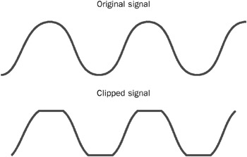
Figure 5.5: Sine wave before and after clipping.
Environmental Reverb Effects
The environmental reverb effect offers a greater amount of flexibility and control than the waves reverb effect when creating virtual reverberant spaces. The Rumpus 3D SFX sample exposes this as a group of preset reverb environments. In the physical world, reverberation consists of not only the late-arriving echoes that create the more obvious effect, but also much shorter reflection paths that arrive very soon after the source sound. These shorter echoes are called early reflections . The environmental reverb effect provides parameters that let you specify how these early reflections behave.
Environmental reverb also provides parameters for adjusting the following properties:
-
The diffusion and density of the late echoes, which allows you to imitate more closely the character of real-world rooms.
-
Rolloff factor, which represents the rate at which the volume level of reflections decreases, or rolls off, as distance increases .
-
The interaction between early reflections and late reverberation, called room effect.
-
Longer reverb decay times than with the waves reverb effect.
Note that environmental reverb does not include the direct, unprocessed sound. You must play the direct sound in a separate buffer, and adjust the levels of the direct sound buffer and the reverb buffer individually to create the desired wet/dry mix.
DirectSound provides 24 default environmental-reverb settings. You may find that these meet your needs. The presets simulate a range of spaces, including a living room, a bathroom, a concert hall, and a parking lot. If you want to experiment with creating your own environmental reverb, you should begin by listening closely to the preset effects using the Rumpus 3D SFX sample. Then review the values associated with the presets by inspecting the definitions for the various constants in the dsound .h header file. Choose a preset that sounds close to the effect that you desire, and use the values from that preset as a starting point when creating your own environmental reverb.
For more information about environmental reverb, see Chapter 7.
Chorus Effect
The chorus effect is aptly named, because the goal of the effect is to create copies of the original sound in a way that tricks the listener into believing that he or she is hearing many sounds in unison ”a chorus. The effect is achieved by creating a duplicate of the source using a short delay, and then modulating the delay time. By modulating the delay time, an impression can be created that many sounds are being created at the same time. Modulating the delay time also introduces slight variations in pitch, which adds complexity to the effect. The effect is not convincing in every instance, but it can make ensemble sounds seem bigger. It can be a pleasing effect on musical instruments like acoustic guitars, and can be an interesting special effect when used to create unnatural sounds.
The modulation effect is achieved by using a low-frequency oscillator (LFO). The LFO creates a fundamental waveform ”in this case, a sine wave or a triangle wave. At a given instant in time, the phase of the LFO is used as a factor to determine the delay time. The frequency and shape of the LFO waveform help to determine the character of the chorus effect.
The DirectSound chorus effect exposes the following parameters:
-
Delay
-
Depth
-
Frequency
-
Waveform
-
Phase
-
Wet/dry mix
-
Feedback
Delay Parameter
The delay ( fDelay ) parameter represents the baseline time for the echo ”the delay time without LFO modulation. The range of possible values for this parameter falls into the category of doubling echo. This means that the time is too short for humans to perceive the echo as a discrete occurrence (the default delay is 16 ms); rather, it sounds like a doubling of the original signal. Shorter delay times make the doubling effect less obvious.
Depth Parameter
The depth ( fDepth ) parameter enables you to adjust the range of variance from the baseline delay time. You can think of this as a level control for the LFO. The greater the depth value, the greater the range of delay times created by the LFO. Depth is specified as a percentage value, with 100 percent yielding the greatest variation in the delay time.
When creating chorus effects for musical instruments, you should use the depth parameter judiciously. High depth values tend to make the modulation effect of the LFO very obvious, which may be desirable for special effects, but can make a musical instrument effect sound unnatural.
Frequency Parameter
You can adjust the rate at which the LFO modulates the delay time by specifying a value for the frequency ( fFrequency ) parameter. The available frequencies are relatively low, between 0 Hz and 10.0 Hz. Specifying lower values for frequency makes the delay modulation occur more slowly, making the effect of the LFO less obvious; higher values can sound like an obvious vibration .
Waveform Parameter
You can alter the shape of the LFO waveform by specifying a value for the waveform ( lWaveform ) parameter. Changing the shape of the LFO waveform enables you to vary the way that the LFO modulates the delay over time. Figure 5.6 shows what the waveform shapes look like. Applying a sine wave shape to the LFO creates a series of delay times that rise and fall gradually. Applying a triangle wave shape to the LFO creates a series of delay times that rise and fall sharply. Which one you choose is a matter of taste and application. You should experiment with each waveform shape to hear for yourself the effect that it creates.
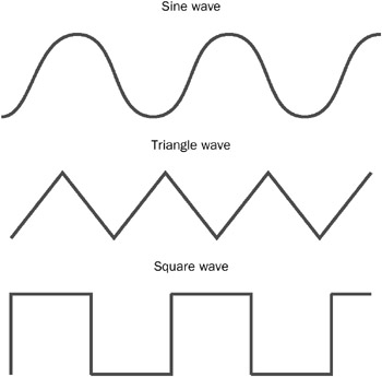
Figure 5.6: Three waveform shapes.
Phase Parameter
The DirectSound chorus effect uses separate LFOs for the left and right channels. The phase ( lPhase ) parameter enables you to adjust how the waveforms for the two LFOs relate to one another in time. When you set this value to zero, the waveforms created by the left and right LFOs match exactly; they are said to be in phase . The result is that the effects for both the left and right channels sound exactly alike.
When you choose a value of 180 or -180, the waveforms become mirror images of each other; they are said to be 180 degrees out of phase . The result is that the left and right channels sound different because, at any given moment, the delay time created by the LFO in each channel is different. (The notable exception is when the waveforms for both LFOs cross the zero point simultaneously .)
Choosing a value of 90 or -90 creates a similar effect, except that the waveforms are not exactly mirror images of each other; they are said to be 90 degrees out of phase or in quadrature phase . Figure 5.7 shows the relationship between two sine waves in quadrature phase.
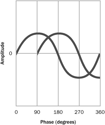
Figure 5.7: Two sine waves in quadrature phase.
The differences created between the left and right channels can create some interesting complexities that give the chorus effect a wider stereo image. This is a parameter that requires some experimentation because the effect is not entirely predictable and varies depending on the source material.
Wet/Dry Mix Parameter
The wet/dry mix ( fWetDryMix ) parameter represents the percentage of processed signal in the final output. Typically, you will want to add some percentage of the processed signal to the original signal to achieve the desired effect, rather than using 100 percent of the processed signal.
Feedback Parameter
As with the echo effect, the feedback ( fFeedback ) parameter represents the percentage of the output signal mixed back into the input buffer. Unlike the echo effect, the chorus effect lets you use a negative value for feedback. When you specify a negative value, the parameter represents the percentage of processed signal subtracted from the input. In either case, the goal is to add to the complexity of the chorus effect by compounding the processing.
Large amounts of positive or negative feedback can drastically change the character of the original sound, because phase interactions introduce frequency-dependent cancellations and reinforcements to the original signal. This can add interesting coloration ranging from hollow to metallic or strangely electronic-sounding. While this type of destructive alteration of the source material might not be appropriate for standard musical fare, it might be just the effect that you want for an alien sound.
Flanger Effect
The flanger effect has a unique sound that is reminiscent of the Doppler effect that you hear when a jet airplane passes overhead. The effect is achieved in an identical fashion to the chorus effect, but the range of delay times used is shorter. When two identical signals that are separated by a very short delay time combine, some audio frequencies cancel each other, while others are reinforced. As the delay time changes, the frequencies at which cancellation and reinforcement occurs also changes. In fact, this is exactly what happens during the Doppler effect. The difference is that the Doppler effect occurs twice (once while the airplane is approaching and again as it moves away), while the flanger effect occurs continuously for as long as the LFO varies the delay time.
The flanger effect has the same parameters as the chorus effect. For details about each parameter, refer to the chorus effect section.
| |
Legend has it that the flanging effect was discovered by accident . In the early days of rock-and-roll recording, time domain effects were achieved by using two synchronized, open -reel tape decks. Each machine received the identical input signal, and then the output signals were combined. During a session that used this technique, someone rubbed up against one of the tape reels, which caused the tape to slow down slightly. The resulting effect sounded interesting. With some experimentation, it was discovered that lightly touching one s finger against the tape reel on one machine and then the other consistently produced the desired effect.
The flat side of a tape reel is called a flange , which is why the effect is named flanging and a device that simulates the effect is called a flanger.
| |
Frequency Domain Effects
The one frequency domain effect provided by DirectSound is ParamEq. This section describes the ParamEq effect and its parameters.
ParamEq Effect
A parametric equalizer is representative of a class of devices, named equalizers, which alter the frequency response of a signal.
Other devices and filter types include:
-
Graphic equalizer This device commonly uses a row of vertically oriented slider controls. Each slider controls a filter that can boost or cut the amplitude of a fixed frequency. The name graphic equalizer comes from the notion that the positions of the sliders give a graphical representation of the change to the frequency response that the device creates. In reality, this isn t true because the combination of the bell-shaped filters results in a change far more complex than the slider positions convey . Graphic equalizers typically can adjust between 5 and 31 bands, depending on the configuration.
-
Notch filter This filter type creates a sharp attenuation within a very narrow frequency bandwidth. Sometimes this type of filter is used to remove a specific noise from the signal, such as hum or buzz.
-
High-pass filter This filter type is an equalizer that attenuates all frequencies below a specified cutoff frequency, leaving only the higher-frequency content in the signal.
-
Low-pass filter This filter type is an equalizer that attenuates all frequencies above a specified cutoff frequency, leaving only the lower-frequency content in the signal.
-
Band -pass filter This filter type is an equalizer that attenuates all frequencies, above and below specified cutoff frequencies, leaving only mid-range frequencies in the signal. You can think of this type of filter as a combination of a high-pass filter with a low-pass filter.
The parametric equalizer is the most flexible type of equalizer. To a great extent, it can do the job of any of the other types of equalizers and filters, simply by altering its settings. This ability to dial in the required settings, or parameters, gives the parametric equalizer its name.
The ParamEq effect can be used as a single effect or as a chain of effects. In the world of electronics, parametric equalizers typically have between two and five bands. This enables you to dedicate one equalizer to a specific part of the audio spectrum, while using another equalizer for another part. For example, you might want to boost some low frequencies to accentuate the bass while attenuating part of the high-frequency range to eliminate noise such as hiss.
It is not a good idea to depend on the ParamEq effect as a way to compensate for problems with your audio source material. Using this effect to fix problems would be far too time-consuming , especially since it is much easier to simply load the sound into commercially available audio-editing software to make changes. The ParamEq effect is a good way for you to provide the user with control over the sound.
The ParamEq effect exposes the following parameters:
-
Bandwidth
-
Center
-
Gain
Bandwidth Parameter
When the ParamEq effect changes the frequency response of the signal, it does so by simultaneously boosting or attenuating a range of frequencies. However, all frequencies are not changed by the same amount. Rather, the frequency response is altered along a bell-shaped curve, with the greatest amount of change occurring at the peak of the curve. This behavior closely matches the way the filter circuits affect the audio signal in an electronic parametric equalizer. Because of the shape of the filter response, this type of equalization is called peaking equalization .
The bandwidth ( fBandwidth ) parameter enables you to adjust the width of the bell-shaped curve. Larger values create a wider curve. The value is given in semitones ; in music, 12 semitones equal one octave . Each semitone corresponds to a unique note name, such as C, G-sharp, E-flat, and so on.
Figure 5.8 shows a graphical representation of peaking equalization. Notice that for each of the three equalization curves shown, the center frequency remains constant, while the range of frequencies affected changes as the bandwidth value changes.
To understand how musical semitones relate to equalization, you first need to know that audible frequencies behave logarithmically with regard to pitch. Each doubling of the frequency results in pitch unison, or one octave. For instance, on a piano keyboard, the A note below middle C has a fundamental frequency of 440 Hz. The A note above middle C has a higher pitch, but sounds like the same note. It has a fundamental frequency of 880 Hz.
It is common to express equalization in terms of fractions of an octave (one-third octave, one-half octave, and so forth). For instance, if you wanted to present the user with a software user interface that imitates a one-third-octave equalizer device, you would create 31 slider controls. Each slider would control a ParamEq effect with a bandwidth of 4 semitones (12 semitones divided by 3).
Center Parameter
The center ( fCenter ) parameter enables you to specify the frequency, in hertz, at which maximum boost or attenuation occurs. Put another way, this is the frequency at which the peak occurs. The range of frequencies available for your use depends on the content in the DirectSound buffer. The maximum frequency permitted cannot exceed one-third the sampling rate. This prevents the ParamEq effect from attempting to process frequencies outside the available range in the content.
For your one-third octave equalizer, each slider control would represent a ParamEq effect with a different value for fCenter . In electronic devices, these are standard frequency values designated by the International Organization for Standardization (ISO).
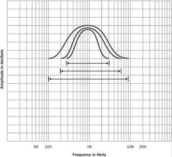
Figure 5.8: Peaking equalization showing three different bandwidths at the same center frequency.
Gain Parameter
The gain ( fGain ) parameter enables you to specify, in decibels, the amount of boost or attenuation at the center frequency, or peak . The available range is from 15 decibels of boost (+15 dB) to 15 decibels of attenuation (-15 dB). Specifying a value of zero means that the equalizer has no effect.
For your one-third octave equalizer, each slider control would vary the fGain value of the ParamEq effect. If the user moves the slider all the way up, fGain equals 15. When the user moves the slider all the way down, fGain equals -15. When the user moves the slider to the center, fGain equals zero.
Amplitude Domain Effects
The following sections describe the following amplitude domain effects and their parameters:
-
Gargle
-
Distortion
-
Compressor
Gargle Effect
The simplest amplitude domain effect is the gargle effect. As you can imagine, this effect causes the audio material to sound like gargling, by using an LFO to modulate the amplitude of the sound.
The Gargle effect exposes the following parameters:
-
Rate
-
Waveform
Rate Parameter
The rate ( dwRateHz ) parameter enables you to specify the frequency of the LFO that creates the effect. Higher values for dwRateHz yield faster-sounding gargle effects.
Waveform Parameter
The waveform ( dwWaveShape ) parameter enables you to specify the type of waveform created by the LFO. Applying a triangle wave shape to the LFO creates a gargle effect with a sharp character. Applying a square wave shape to the LFO creates a gargle effect with an even more abrupt modulation. Which one you choose is a matter of taste and application. You should experiment with each waveform shape to hear for yourself the effect that it creates.
Distortion Effect
Distortion ( specifically , harmonic distortion) is a change in the sound that happens when the amplitude of the signal exceeds the available range. The result is that additional harmonic artifacts are created as the shape of the waveform is changed, or clipped . You have probably heard distortion before; it is that fuzzy sound that happens when, for instance, a speaker is damaged.
Usually, distortion is something that audio engineers seek to avoid because it changes the sound in unwanted ways. However, sometimes distortion is a desirable effect, most frequently used in electric guitar amplifiers . The signal that an electric guitar creates tends to have a clean, pure sound. Deliberately adding some distortion to the signal can make the sound more interesting. The DirectSound distortion effect is designed to create this kind of sound.
Of course, you don t have to use the distortion effect strictly to enhance musical instruments. You might use it to create a special effect for your game. For example, this effect can create the impression of a noisy radio transmission.
The distortion effect exposes the following parameters:
-
Edge
-
Post-EQ center frequency
-
Post-EQ bandwidth
-
Pre-lowpass cutoff
-
Gain
Edge Parameter
The edge ( fEdge ) parameter enables you to specify the intensity of distortion in the output signal. (Distortion is often characterized as having an edgy sound.) Values close to 100 percent tend to make the output signal sound unintelligible, so usually you will want to use values less than 50 percent.
Post-EQ Center Frequency Parameter
Although the distortion effect is classified as an amplitude domain effect, the extra harmonics that make the sound distorted are created in the frequency domain. This means that frequency-domain processing like equalization can have a profound impact on the sound of the distortion effect. The DirectSound distortion effect provides a single band of peaking equalization that you can use to accentuate the effect. The equalization provides a fixed amount of boost, but you can adjust the center frequency and the bandwidth.
The post-EQ center frequency ( fPostEQCenterFrequency ) parameter enables you to specify the peak frequency for the equalizer.
Post-EQ Bandwidth Parameter
The post-EQ bandwidth ( fPostEQBandwidth ) parameter lets you adjust the range of frequencies (relative to the center frequency) that are boosted. You specify this range in hertz. Wider-range values result in more harmonics being generated, thereby resulting in denser-sounding distortion.
Pre-lowpass Cutoff Parameter
Because the harmonics that make up the audible distortion signal are higher multiples of fundamental frequencies, it is useful to filter out high-frequency content from the original signal before creating distortion. To enable this, the distortion effect provides the pre-lowpass cutoff ( fPreLowpassCutoff ) parameter. This value represents the frequency above which all frequencies are attenuated.
Gain Parameter
The gain ( fGain ) parameter lets you adjust the volume of the output of the effect. The default value is -18 dB. Specifying values higher than the default (closer to 0 dB) provides an increase in volume; lower values provide a decrease in volume.
Compressor Effect
Dynamic compression is the process of reducing the dynamic range of a signal in response to changes in signal level. In the analog world, this is accomplished by using an amplifier with an output gain that varies in response to the input level. When the amplifier s input exceeds a predetermined level, called the threshold , the circuitry reduces the output gain by a predetermined amount. The amount of gain is usually expressed as a ratio. For example, a 3-to-1 ratio means that for every 3 dB by which the input signal exceeds the threshold, only 1 dB of gain occurs at the output.
Dynamic compression can be used for several purposes. First, it is useful to help prevent an input signal from exceeding the dynamic range of the medium. For instance, if you were to record a source with a 110 dB dynamic range as a 16-bit digital signal, you would need to compress the dynamic range by about 14 dB because 16-bit digital audio has a 96 dB dynamic range. To be absolutely sure that the signal never exceeds the dynamic range, you can use a very high compression ratio with a threshold close to the limit of the medium. This type of compression is called limiting .
Dynamic compression is also used as an effect. A little bit of compression can help make a musical performance sound better. For instance, if a particular vocalist is inconsistent with his or her microphone usage, a compressor can even out the dynamics. If the vocalist is performing with a loud band, the compression can ensure that each syllable of each word can be heard and understood . Keep this idea in mind when mixing sounds for your game soundtrack, because the compressor effect might be able to fix problems in the source sounds.
The compressor effect exposes the following parameters:
-
Threshold
-
Ratio
-
Pre-delay
-
Attack
-
Release
-
Gain
Threshold Parameter
You can set the threshold for the compressor effect by specifying a value for the threshold ( fThreshold ) parameter. This parameter lets you set the volume level at which the compression effect engages. This parameter has a maximum value of zero, which represents digital full scale. Other values are specified in decibels below full scale.
The dotted line in Figure 5.9 represents the threshold. Notice how the output level with compression is consistently lower above the threshold than with no compression.
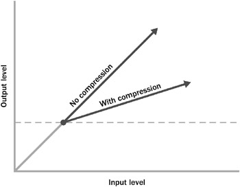
Figure 5.9: Signal amplitude before and after compression.
The value that you choose for this parameter depends on the dynamics of the source material and the effect you are trying to achieve. If you set the threshold higher than the maximum signal level, no compression will occur. If you set it too low, you risk limiting the dynamics of the source material, which can make the audio turn dark or muddy sounding.
Ratio Parameter
The ratio ( fRatio ) parameter lets you specify how much gain reduction occurs when the threshold level is exceeded. For instance, a value of 3 represents a 3-to-1 compression ratio.
Again, the value you choose for this parameter depends on the content. High values (greater than 10) make the effect behave like a hard limiter. This can be useful if you want to ensure that the volume of the material doesn t ever exceed some particular level. The range between 2 and 10 represents the most commonly used settings. In this range, the effect can be more subtle, less noticeable, while still helping to smooth out the dynamics of the content.
Pre-delay Parameter
Some sounds start with a sharp part, called the attack , followed by a lower-level sustained portion, which is then followed by a decaying portion, called the release . For example, think of a piano note. When you press a piano key, a hammer inside the piano momentarily strikes a taut wire. The hammer strike creates the attack portion of the sound. Once the hammer moves away from the wire, the note sustains and decays for as long as the piano key is depressed.
Now, suppose you want to apply some compression to a piano soundtrack. You want to help even out the dynamics of the performance to keep it audible, but you also need to maintain the relationship between the hammer strikes and the sustaining notes. In other words, you don t want the compressor effect to engage every time that a hammer strikes a wire, because this would change the very nature of how the piano sounds.
You can prevent the compressor effect from functioning too soon by specifying a value for the pre-delay ( fPredelay ) parameter. Pre-delay introduces a very short hesitation before the compressor effect engages after the compression threshold is exceeded. This is an ideal way to prevent compression of the attack portion of a sound.
Attack Parameter
The attack ( fAttack ) parameter enables you to specify how long it takes for compression to reach the specified ratio. For instance, suppose you set a ratio of 10 to 1. If the compressor effect reduces the volume by that ratio instantly each time the level exceeds the threshold, the result can be a pumping effect when the volume changes introduced by compression become obvious. Specifying a longer attack time causes the effect to ease in more gradually. Conversely, if you want the compression to happen right away, specify a very short time for the attack parameter.
Release Parameter
Like the attack parameter, the release ( fRelease ) parameter affects the way the compressor effect behaves over time. When the level drops below the threshold, the compression takes some amount of time to disengage, or release. How suddenly this happens depends on the time that you specify for the release parameter.
Gain Parameter
The gain ( fGain ) parameter allows you to change the output level of the effect. Typically, this is most useful for make-up gain. Often, the end result of applying the compressor effect is that the average volume of the program material lowers. By adding some gain after the compression, you can restore the apparent volume level of the material after reducing the overall dynamic range. This helps to make the softer portions sound louder.
EAN: 2147483647
Pages: 120